| Command | CAPCAD_CURVE_TOOLS (Curve Utilities) |
| Shortcut | none |
| Ribbon | CapCad tab › CAD Utilities panel › Geometry split button › Polyline Utils (the tooltip is what reads Curve Utilities) |
| Category | CAD Utils: Segment |
| Form | CurveUtilitiesForm — Polyline Utilities, modeless, single instance, seven tabs |
| Hosts | AutoCAD, BricsCAD, GstarCAD, ZWCAD and ARES Commander. The window opens on all five, but seven of the operations only work on AutoCAD — see Notes |
| Also opened by | none. CAPCAD_AREA_TRIM, covered in Draw and modify, is the Area Trim tab without the form and without options |
| Concepts | Layers and the Layer Catalogue |
Twenty-three geometry operations that work the whole selection at once, not one curve at a time. It is the window for tidying up a drawing that came from outside: convert everything to polylines, find the duplicates, remove the vertices that serve no purpose, trim against a boundary and close what is left open.
- Trim by area, not by intersection. You pick a closed boundary and a selection; whatever is on the wrong side disappears, with the arcs cut at the right curvature.
- One operation at a time, on purpose. The option buttons are exclusive across all seven tabs: no accidental combination of two operations in one pass.
- A single Undo. On AutoCAD, everything the Ok does goes into one undo group, even when it is thousands of entities.
- Overlap checking built in. Identical geometry and overlapping stretches, the two classic vices of a drawing that has passed through many hands.
- Union of closed boundaries. Several polygons become one boundary, with the offset factor that welds entities that merely touch.
- Nothing is selected in the dark. The operations that need a boundary or a single curve ask for that piece before the general selection.
How the window works
Seven tabs — Area Trim, Convert, Analyze, Modify, Extract, Add and Util — and on each of them a list of blue option buttons. The buttons are mutually exclusive across all the tabs: selecting one clears whatever was selected on any other. On opening, none is selected.
The Ok (2) runs the selected option, always in the same order:
- The window hides.
- If the operation does not make its own selection, the CAD asks Select objects:. Nothing selected ends the pass — silently, with no warning (see Notes).
- The undo group opens, the operation runs, the group closes. Outside AutoCAD there is no grouping: each entity drawn or erased is an undo step of its own.
- The window reappears.
Nine operations make their own selection before anything else: the two area trims, Convert 3D to 2D (17), Offset all (29), Remove redundant straight vertices (31), Hatch to boundaries (12), Select entities by geometry touching it (40), Number vertices (41) and Union (43).
The footer's Delete inputs (1) box, ticked from the factory, does not apply to every operation: it is only read by Curve with width to boundary (10), Offset all (29) and Hatch solid (37). Many others delete the source entities always, and some never delete — the table at the end of the page sums that up.
Area Trim tab
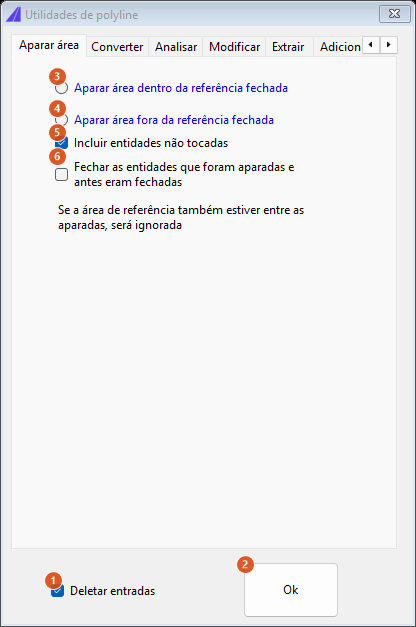
The screenshots on this page are of a Portuguese session; the numbering is the same in both editions, and the tables give the English captions.
| # | Control | What it does |
|---|---|---|
| 3 | Area trim inside closed reference | Removes what is inside the boundary and keeps what is outside. |
| 4 | Area trim outside closed reference | The opposite: keeps only what is inside. |
| 5 | Include not touched entities | Ticked from the factory. It concerns entities that lie wholly in the removal zone without ever crossing the boundary: ticked, they are deleted as well; unticked, they survive. The name misleads — "include" means include in the trim, not in the result. |
| 6 | Close entities that were trimmed and were closed before | For a closed source entity, re-closes each surviving piece by walking the boundary itself between its two ends. Without it, what is left of a trimmed polygon is an open curve. Unticked from the factory. |
The warning If reference area selected amongst the trimees as well will be ignored is literal: the boundary is compared with each entity of the selection and skipped when it matches.
Workflow
- Select (3) or (4) and click Ok.
- The first time in each session, a reminder explains the order of the two selections.
- Select 1 EDGE, and then after ent's to be trimmed… — pick the boundary, a single curve.
- Select objects: — pick what is to be trimmed. Above 1000 entities the command asks for confirmation, saying how many there are (Wish to process N entities?).
- The surviving pieces are drawn and the source entities are deleted, whether or not the Delete inputs box (1) is ticked.
Three cases in which the trim gives the drawing back looking as it was, with no warning: a boundary that is a single straight line (a straight line does not bound an area), a boundary that crosses itself, and an invalid boundary. In all three the geometry is unchanged, but the selected entities are still erased and redrawn as new entities — so their handles change, and anything keyed to them is lost.
Convert tab
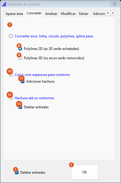
| # | Control | What it does |
|---|---|---|
| 7 | Convert arc, line, circle, polylines, spline to: | Redraws the whole selection as polylines. The source entities are always deleted. |
| 8 | 2D polylines (3D will be flatten) | Selected from the factory. Clicking into it also selects button 7. |
| 9 | 3D polylines (arcs will be removed) | The same, with 3D polyline output. AutoCAD only; on the other CADs the output comes out in 2D with a warning. |
| 10 | Curve with width to boundary | For each element of the selection, turns the polyline's width into a closed boundary. An element with no width stops the operation with an error. |
| 11 | Add hatch | Ticked from the factory. Fills the boundary with a solid hatch, boundary included. Unticked, only the boundary comes out. AutoCAD only — on the other CADs it is skipped silently, with no warning. |
| 12 | Hatch to boundaries | Makes its own selection and converts each hatch chosen into the curves of its boundaries. AutoCAD only. |
| 13 | Delete inputs | Ticked from the factory. This is operation 12's own box — it deletes the source hatches. Not to be confused with the footer's box 1. |
Analyze tab
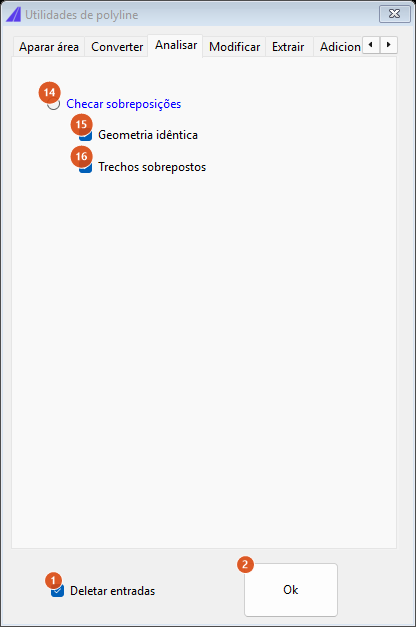
| # | Control | What it does |
|---|---|---|
| 14 | Check overlappings | Looks for duplicates in the selection and highlights them. AutoCAD only. |
| 15 | Identical geometry | Ticked from the factory. Looks for entities with exactly the same geometry. |
| 16 | Bits overlaping | Ticked from the factory. Looks for different curves that share a stretch. |
Modify tab
This is the big tab — ten operations, each with its own fields.
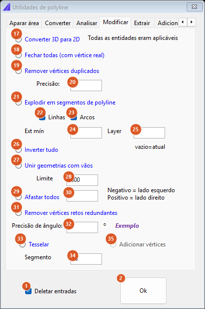
| # | Control | What it does |
|---|---|---|
| 17 | Convert 3D to 2D | Flattens the selection in Z. Makes its own selection. AutoCAD only. |
| 18 | Close all (with real vertice) | Closes each open curve by adding a real vertex back at the first point, not merely by turning on the CAD's closed flag. Deletes the originals. |
| 19 | Remove Duplicate Vertices | Removes coincident vertices. The originals are deleted before the redraw. |
| 20 | Precision: | The tolerance of the comparison. Empty or zero uses the default precision. |
| 21 | Explode to polyline segments | Each span becomes a two-vertex polyline; an arc span keeps its bulge. The originals are not deleted. |
| 22 | Lines | Ticked from the factory. Includes the straight segments. |
| 23 | Arcs | Ticked from the factory. Includes the arc segments. |
| 24 | Ext min | 0 from the factory. Segments shorter than this value are discarded; at the default of zero the filter is skipped entirely. |
| 25 | Layer | Empty from the factory: the segments come out on the current layer. Filled in, the layer is created if missing and receives the segments. The layer gets exactly the name you type, independent of the active style (see Notes). |
| 26 | Reverse all | Reverses the walking direction of every curve of the selection. The originals are deleted and redrawn. |
| 27 | Join geometries with gaps | Splices curves separated by a gap, and then joins the ones that end up touching (tolerance 0.001). |
| 28 | Limit | 3000 from the factory: the largest gap the splice accepts. |
| 29 | Offset all | The batch offset. Makes its own selection. Zero answers that the offset value cannot be zero and draws nothing. |
| 30 | (offset value) | Empty from the factory. Positive offsets to the right of the curve's walking direction, negative to the left — which is what the label beside it says. |
| 31 | Remove redundant straight vertices | Works on one curve only, picked at the time (Select geometric entity…): it deletes the original, removes the vertices that do not change direction and redraws, reporting how many went. |
| 32 | Angle precision: | 1 from the factory, in degrees: the change of direction below which a vertex is considered superfluous. |
| 33 | Tesselate | Rewrites each curve as a sequence of straight segments. Deletes the originals. |
| 34 | Segment | 10 from the factory: the length of each segment. Zero or negative stops the operation with an error. |
| 35 | Add vertices | Not available in this version. |
The Sample link, beside the angle precision, downloads and opens sample-polylines-vertex-optimization.dwg from the CapCad server after asking Sample file will be open - proceed?. AutoCAD only.
Offset all (29) deserves a note of its own: it uses the CAD's own offset and, unlike CAPCAD_OFFSET, does not fall back to CapCad's own offset when the CAD refuses — each refusal becomes a message, and the total number of failures appears at the end. Each new curve inherits the properties (layer, colour, linetype) of the one that generated it. On the four non-AutoCAD hosts the pass uses CapCad's own offset instead, and there the Delete inputs box has no effect: the source curves are never erased.
Extract tab
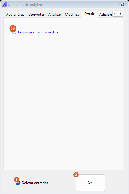
| # | Control | What it does |
|---|---|---|
| 36 | Extract vertices points | Marks every vertex of the selected curves with a POINT entity. The curves stay. |
It is the only operation released without a licence: with no valid licence the command still opens the window, says Point utilities free version: only some options enabled. and disables every option but this one. (Every option button is blue anyway; what actually marks this one out is that all the others grey out.)
Add tab
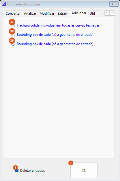
| # | Control | What it does |
|---|---|---|
| 37 | Hatch solid individually all closed curves | One solid hatch per closed curve of the selection; open curves are ignored. The boundary is not redrawn. AutoCAD only. With box 1 ticked, the originals are deleted before hatching. |
| 38 | Bounding box all (input only geometry) | A single enclosing rectangle for the whole selection. |
| 39 | Bounding box each (input only geometry) | One enclosing rectangle per entity. |
In both bounding box cases the originals stay.
Util tab
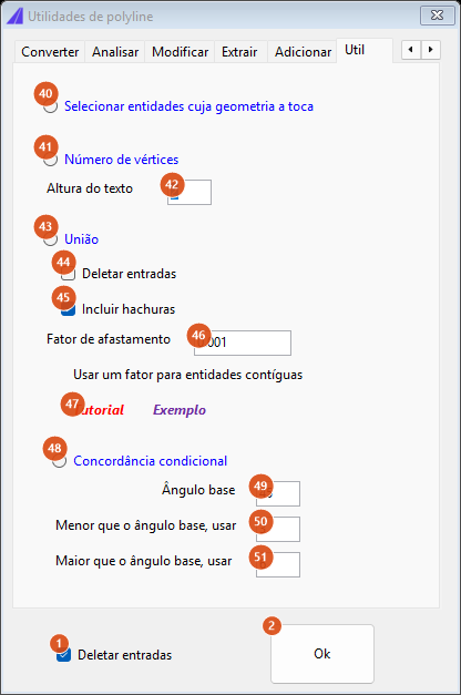
| # | Control | What it does |
|---|---|---|
| 40 | Select entities by geometry touching it | Asks for a curve and leaves everything it crosses or touches selected in the CAD. It draws and deletes nothing. AutoCAD only. |
| 41 | Number vertices | Asks for one curve and writes, beside each vertex, its number — starting at 1, and without numbering the last vertex. The text sits 4 drawing units from the vertex, in the direction opposite the corner's bisector. AutoCAD only. |
| 42 | Text height | 2 from the factory. With 0, the height is the diagonal of the curve's bounding box divided by 20. |
| 43 | Union | Makes its own selection and merges its closed boundaries into one, drawn in red and at the top of the draw order. AutoCAD only. |
| 44 | Delete inputs | Unticked from the factory. This is the union's own box — it deletes the source entities. |
| 45 | Include hatches | Ticked from the factory: the boundaries of the selected hatches enter the union. Unticked, the hatches are discarded. Open curves are always discarded, and the total discarded is reported at the end. |
| 46 | Offset factor | 0.001 from the factory. Each boundary is inflated by this value before the merge, which makes two entities that merely touch genuinely overlap. Without it, contiguous boundaries do not join. |
| 47 | Tutorial | Opens CapCad's YouTube channel. |
| 48 | Fillet conditional | Fillets the corners of each selected curve with two different radii, chosen by the angle of the corner. Deletes the originals. |
| 49 | Base angle | 45 from the factory, in degrees: the threshold that separates the two radii. |
| 50 | Less than base angle, use | 3 from the factory: the radius for corners tighter than the threshold. |
| 51 | Greater than base angle, use | 6 from the factory: the radius for the more open corners. |
The Sample link, beside Tutorial, downloads and opens sample-polylines-union-all.dwg.
The footer
| # | Control | What it does |
|---|---|---|
| 1 | Delete inputs | Ticked from the factory, but read by only three operations: Curve with width to boundary (10), Offset all (29) and Hatch solid (37). |
| 2 | Ok | Runs the selected option. |
Who deletes the source entity
| Operations | Deletes the original? |
|---|---|
| Area trim (3, 4), Convert to polyline (7), Remove duplicate vertices (19), Reverse all (26), Join with gaps (27, when it works), Close all (18), Tesselate (33), Remove redundant straight vertices (31), Fillet conditional (48) | always, whether or not box 1 is ticked |
| Curve with width to boundary (10), Offset all (29), Hatch solid (37) | according to the Delete inputs box (1) |
| Hatch to boundaries (12), Union (43) | according to the operation's own box (13, 44) |
| Explode (21), Bounding box (38, 39), Extract points (36), Check overlappings (14), Select by touching (40), Number vertices (41) | never |
Remembered between sessions
Nothing. The window stores no preference: on every CAPCAD_CURVE_TOOLS the tab goes back to Area Trim, no option stays selected and every field returns to its factory value (0, 3000, 1, 10, 2, 0.001, 45, 3, 6). The window is single instance, so running the command again only brings back the one already open — with whatever you had typed into it.
Notes
- Seven operations only work on AutoCAD. On the other CADs the window opens normally and each answers
<name>is not available on this CAD host yet: hatch to boundaries (12), check overlappings (14), convert 3D to 2D (17), hatch solid (37), select by touching (40), number vertices (41) and union (43). The 3D polylines sub-option (9) gives the same message and then draws in 2D anyway, and the two Sample links give it as well. - Off AutoCAD, two options are not applied. Add hatch (11) is skipped, so Curve with width to boundary draws the bare boundary; and Offset all (29) ignores the Delete inputs box, so the source curves are never erased. Offset all itself works on all five, but outside AutoCAD it runs on CapCad's own offset rather than the CAD's.
- "Include not touched entities" (5) deletes; it does not keep. Ticked — the default — it also deletes the entities that sit wholly in the removal zone without ever crossing the boundary. If the intention is to preserve those entities, untick the box. The command-line
CAPCAD_AREA_TRIMbehaves the other way round: it always passes the flag off, so it keeps entities that never touch the boundary. - The footer's "Delete inputs" box (1) governs three operations, not twenty-three. The rest decide on their own, and several always delete. Check the table above before running an operation on a drawing you cannot redo.
- With no selection, the Ok says nothing. If you press Enter at the Select objects prompt without picking anything, the window comes back and nothing happens — there is no message.
- With no option selected, the Ok asks for the selection and gives the window back. Since no button starts selected, the first Ok of a new session only asks Select objects and gives the window back. Select the operation first.
- The label All entities were applicable, on the Modify tab, is a fixed text that always shows, even before any operation.
- The Layer field (25) creates the layer with exactly the name you type, without the style's prefix, without the colour and without the linetype the role would carry. To get the right layer, create it first in Drawing Standards (see Layer Tools) and paste here the name shown there in the Layer CAD column.
- The offset of Offset all (29) has the opposite sign to the offset assistant's. Here, positive goes to the right of the walking direction; in the Offset Assistant and the Variable Offset positive goes to the left.
- The area trim does not trim self-intersections: a concave boundary can produce loops. Check the result.
- Several prompts are in English on every profile — Select 1 EDGE, and then after ent's to be trimmed…, Select objects, and the unavailability messages on the other CADs.
- The ribbon button is labelled Polyline Utils. It is the tooltip that carries the real name, Curve Utilities. It sits on the Geometry split button, beside the Single Curve Assistant and the Variable Offset.
See also
- Polyline and segment tools — the same families of operation, but one curve at a time, from the command line.
- Draw and modify —
CAPCAD_AREA_TRIM, which is the Area Trim tab with no window and no options. - Single Curve Assistant — fillets, chamfers and tangency, vertex by vertex.
- Offsets — the plain offset, the assistant and the variable offset.