| Command | CAPCAD_SIGN_MANAGE |
| Shortcut | none |
| Ribbon | CapCad tab › Road Signing panel › Signs split button › Road Signs Management |
| Category | Vertical |
| Form | VerticalManageForm, titled "Manage Vertical" (modeless: the drawing stays live while it is open) |
| Hosts | AutoCAD, BricsCAD, GstarCAD, ZWCAD, ARES Commander |
| Also opened by | CAPCAD_ANALYTICS_SIGN_POST_HEIGHT (same form, opened straight on the Support height tab; ribbon › Project panel › Analytics split button › Road Signs: Post Height) |
Every sign in the drawing in one list, and every support length worked out for you. The CAD on its own lists blocks; it does not know what a sign is, what a support is, or which support belongs to which sign.
- A full inventory in one click. Sweeps model space, recognises signs by their attributes, measures each one's real area from the block geometry, and brings back the chainage, the action and the handle.
- Filters that answer as you type. Area, width, height, a chainage range and a code; the total area of the filtered list appears as you go.
- From the list to the drawing. Click a row (or several) and the sign is selected in the CAD, with the option to zoom or pan to it and to bring the paired support along.
- Support lengths, not a side spreadsheet. Embedment, clearance, number of columns and foundation come out of a built-in table and your own options.
- The result stays in the drawing. The measurements are written as XData on the support block, the
SUP_Hattribute is filled in, and the cross-section can be drawn at real size. - The same tool on five CADs. AutoCAD, BricsCAD, GstarCAD, ZWCAD and ARES Commander.
What it does
The command opens a three-tab form that works on the signs already inserted in the drawing.
The Manage vertical tab builds the inventory: it walks every attributed block in model space, separates signs from supports, pairs each sign with its support, and builds a table of code, area, width, height, chainage, action and the sign's handle. From there you filter the list and use the list as a selector: clicking a row selects the sign in the drawing.
The Support height tab does the construction sizing. For one chosen support (or a selection of supports) it reads the sign seated on it, takes width and height from the block geometry, works out the embedment depth and the number of columns from a built-in table, adds the clearance and the sign height, and returns the total length of each post. The result is written as XData on the support block, written into the SUP_H attribute, presented in a text report and, optionally, drawn as a cross-section and as a plan layout.
The Support height - options tab is a shortcut to the neighbouring commands (Reports, 3D, XData) and states the method used when a support has more than one column.
Two notions carry the whole page:
- A sign is an attributed block carrying one of the sign identification keys (
SIGN_CODE,SENAL_COD,CODIGOPLACA,PLACA_CODorCODIGO). - A support is an attributed block carrying
POST_CODEorSUP_COD. The pairing between the two is geometric: the support has a seating point for the sign (the dynamic parameter "Position2 X/Y" turned by the block's rotation), and the sign counts as its own when its insertion point coincides with that seating point to within 1 drawing unit on each axis.
Conventional signs get separate treatment: in the inventory they come in with area, width and height zeroed, and in the height calculation their size is read from the dimension attribute rather than from the geometry. "Conventional" here means a fixed list of short codes — a letter, a hyphen and a number, at most 5 characters once the style suffix is stripped. On other country profiles no sign matches, so every sign is measured from its block geometry and the Include conventional filter has no effect.
Workflow
Inventory the signs
- Run
CAPCAD_SIGN_MANAGE. The form opens on the Manage vertical tab. - Click Process (11). Every sign in model space enters the table, ordered by chainage.
- Filter down to what matters: Area limit (2), Width limit (3), Height limit (4), the Limit to … to … km range (5, 6) or the Code (7). Clear Include conventional (10) to leave only the non-conventional signs.
- Check the count on the left ("N signs") and the Total area (13) of the filtered list.
- Choose what a row click does: Zoom, Pan or No zoom (14, 15, 16), and what it should select: Select sign (17), Select support (18) or both.
- Click a row — or drag across several — to take the selection to the drawing. The selection stays active: the next CAD command already uses it.
Work out the support lengths
- Go to the Support height tab (or run
CAPCAD_ANALYTICS_SIGN_POST_HEIGHT, which opens straight on it). - Set the options: Terrain and carriageway (31, 32), Clearance (41 to 46), Embedment depth (47 to 50), Foundation (51 to 56) and the roundings (33 to 36).
- Click Select individual support (20) and pick a support block, or Multiple selection... (29) and build a selection. The form hides while you pick and comes back afterwards.
- Read the report: in single mode, if Final message (21) is ticked; in multiple mode, if Final report (30) is ticked.
- The status line at the bottom shows what was done and, in brackets, the problems found.
Each run writes the measurements onto the support block. Running again with other options overwrites the previous values.
The form
The numbers are the same in every screenshot of this page: one numbering across all three tabs.
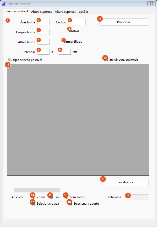
Tab 1, "Manage vertical": filters at the top, the table in the middle, the click behaviour at the bottom. The table is empty until you click Process.
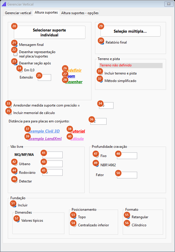
Tab 2, "Support height": single mode on the left, multiple mode and the terrain state on the right; the three calculation frames below.
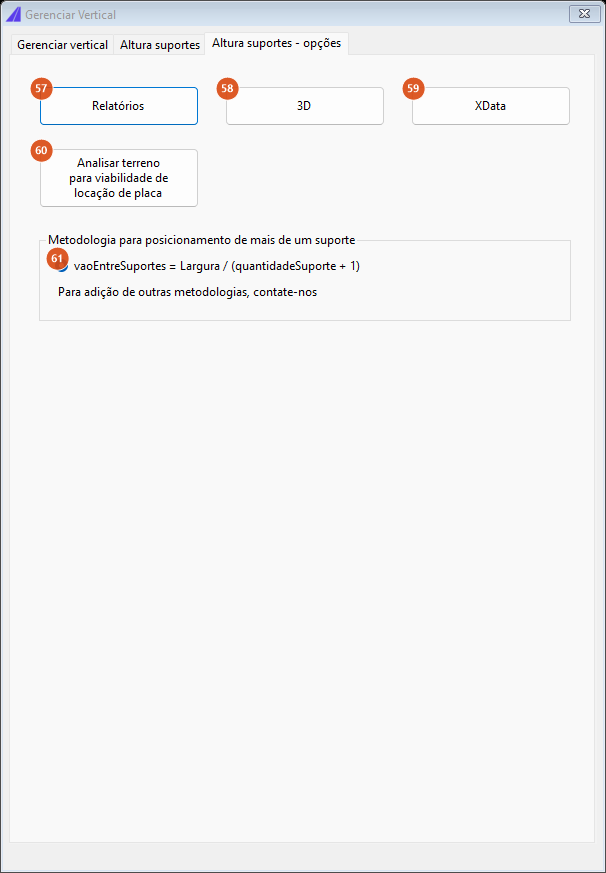
Tab 3, "Support height - options": shortcuts to the neighbouring commands, and the method for placing more than one support.
Tab 1: Manage vertical — filters
Every filter reacts as you type; there is no apply button. An empty (or zero) field filters nothing.
| # | Control | What it does |
|---|---|---|
| 1 | ? | Opens the reminder about the area calculation. |
| 2 | Area limit | Keeps only the signs whose area is greater than or equal to this value, in m². |
| 3 | Width limit | Keeps only the signs at least this wide, in metres. |
| 4 | Height limit | Keeps only the signs at least this tall, in metres. |
| 5, 6 | Limit to … to … km | A chainage range, inclusive at both ends. The values are multiplied by 1000 and compared with the sign's chainage in metres. Two points: the second field on its own does not switch the filter on, and the first field filled with the second empty empties the list (the range becomes "from km1 to 0"). Fill in both. |
| 7 | Code | Text contained in the code, case-insensitive. While this field has text it overrides every other filter, Include conventional included; clear it and the full list comes back. |
| 8 | Reset | Clears only Area limit and Width limit. |
| 9 | Clear filters | Clears all six fields: area, width, height, the two chainages and the code. |
| 10 | Include conventional | Ticked (default): the list holds every sign. Cleared: the conventional signs leave the list. |
| 11 | Process | Sweeps model space, builds the inventory and fills the table. It is the only control that reads the drawing; the filters work on the result of that last sweep. |
Tab 1: the table and the selection
| # | Control | What it does |
|---|---|---|
| 12 | table | One row per sign, read-only, full-row and multiple selection. Columns: codigo, area, width, height, ext, ação and ID. See below what each one holds. |
| 13 | Total area | The sum of the area column over the displayed rows, updated on every filtering. |
| 14 | Zoom | On a row click, centres the view on the chosen entities and sets the window to three times their extent. |
| 15 | Pan | Default. Centres the view on the entities without changing the zoom. |
| 16 | No zoom | A click in the table neither selects nor moves the view. Use it when you only want to read the list. |
| 17 | Select sign | Ticked (default): the row's sign goes into the selection. |
| 18 | Select support | Ticked (default): the support paired with that sign goes in too. If both are cleared, the sign is selected anyway. |
| 19 | Locator | Not available in this version; the status line says so. |
The "Multiple selection possible" label above the table is a reminder: you can drag across several rows before releasing the button, and they all go into the selection at once. At the left of the footer, a grey label shows the number of displayed rows ("N signs").
Table columns:
| Column | Content |
|---|---|
codigo |
The sign's code attribute; if that is empty, the block's effective name. In both cases the category prefix and the style suffix ("-GrayShaded", "-OBRA", …) are stripped. |
area |
Width × height, in m², to two decimals. Measured on the geometry of the block definition, ignoring attributes, text and hatches. Conventional signs come out as 0.00. |
width, height |
Width and height of the same measurement, in metres. Conventional signs come out as 0.00. |
ext |
Chainage in metres. Read from the sign's km attribute (with the text "Km" stripped). See the note about the alternative alignment-based calculation in Notes. |
ação |
The sign's long-form action attribute, as stored. Empty on conventional signs. |
ID |
The sign's handle in the drawing — it is how the row click finds the entity. |
The table comes out sorted by ext, ascending.
Tab 2: Support height — single run
| # | Control | What it does |
|---|---|---|
| 20 | Select individual support | Hides the form and asks for a block in the drawing. If you pick a sign instead of a support, the command says so and stops. Before calculating, the drawing is swept again so the work is done on the current state. |
| 21 | Final message | Ticked (default): when it finishes, opens the "H suporte" report window with the calculation memo in a fixed-pitch font. |
| 22 | Draw the real sign/support representation | Draws the plan layout: a 10 cm circle at each column position, on layers CAPCAD_VERTICAL_LOCAÇÃO_1, _2, _3 (colours 1, 2, 3), plus a polyline of width 0.10 the width of the sign, on layer CAPCAD_VERTICAL_LOCAÇÃO (colour 3). It applies to the multiple run too. |
| 23 | Draw section after | Ticked (default): after the calculation, builds the assembly's cross-section. Single run only. |
| 24 | At 0,0 | Ticked: the section is drawn where it was built, at real levels (therefore far from the drawing origin, at the terrain elevation). Cleared (default): the command asks for an insertion point and moves the section's bottom centre to it. |
| 25 | Length | Length of the terrain line in the section, in metres. Default 4; empty or zero falls back to 2. |
| 26 | Reset | Erases the entities of the last section drawn. |
| 27 | Zoom | Zooms to the last section built, with 20 % margin. |
| 28 | Draw | Draws the last section built again, without redoing the calculation. |
The section is drawn on layers CAPCAD_HSUPORTE_SECTION_PISTA (the carriageway line and its level), CAPCAD_HSUPORTE_TERRAIN (the terrain, with the closed fill), CAPCAD_HSUPORTE_FUNDACAO (the foundation blocks) and CAPCAD_SUPORTE_TEXTO (the memo, as MText). The posts go on the current layer, with a width of 0.03. The sign blocks are inserted with a handful of attributes copied from the original sign.
Tab 2: multiple run and terrain
| # | Control | What it does |
|---|---|---|
| 29 | Multiple selection... | Hides the form and asks for a selection. Every block in it that is a support is calculated; anything else is ignored silently. It draws no section. |
| 30 | Final report | Ticked (default): when it finishes, reports how many supports were found and opens the "H suportes" window with the memos concatenated. If any sign was left with an undeterminable height, the message changes to ask you to check the report; if no valid support was found, it says so. |
| 31 | Include terrain and carriageway | Uses the digital terrain model: each column's level comes from the surface, and the carriageway level comes from the surface at the foot of the perpendicular to the project alignment. It is only enabled when both an alignment and a terrain exist; the grey label just above says which of the two is missing and turns green when both are set. |
| 32 | Simplified method | Default. Works at level zero: the difference between the carriageway level and the support level drops out of the sum, and the support length becomes embedment + clearance + sign height. |
The surface comes from the LandXML named in the project configuration. If terrain is asked for and there is no surface, the calculation goes on without it and the status line records TerrenoNaoEncontrado.
Tab 2: measurements
| # | Control | What it does |
|---|---|---|
| 33 | Round the support length to a precision of = | Rounds the support length up to the next multiple of box 34. The difference is absorbed by the buried part, which grows by the same amount. |
| 34 | value | The rounding multiple. Default 0.5. |
| 35 | Include calculation report | Also writes as XData the intermediate values — clearance, carriageway level difference and buried length of each column — which otherwise appear only in the report. |
| 36 | Distance for signs in an assembly | The gap between two signs stacked on the same support, in metres. Default 0.2. It only enters the sum when the support has a second sign; stacked assemblies are not recognised in this version (see Notes). |
| 37 | Sample Civil 3D | Opens a notice saying Civil 3D is needed for that sample and pointing at the LandXML route for other CADs. |
| 38 | Tutorial | Opens the tutorial video in the browser. |
| 39 | Sample LandXml | Not available in this version; the status line says so. |
| 40 | Calc. | Shows the formula for the final length: buried length + ground-to-underside-of-sign length (the clearance) + sign height + the difference between the carriageway level and the level at the sign's siting point (positive or negative). |
Tab 2: Clearance
Clearance is the distance from the ground to the bottom edge of the sign.
| # | Control | What it does |
|---|---|---|
| 41 | MQ/MP/MA | The clearance used when the sign is a kilometre post, a position marker or an alignment marker. Default 1. It applies to a fixed list of block-name prefixes and, in those cases, replaces the urban or rural value. |
| 42 | Urban | Uses the clearance in box 43. |
| 43 | urban value | Default 3.0 m. |
| 44 | Rural road | Selected by default. Uses the clearance in box 45. |
| 45 | rural value | Default 1.5 m. |
| 46 | Detect | Automatic detection of the stretch is not available in this version. When it is selected the calculation uses the rural value and the status line records VaoDetectarDeferred. |
Check both values against the norm of the active country profile: they are defaults, not requirements.
Tab 2: Embedment depth
| # | Control | What it does |
|---|---|---|
| 47 | Fixed | Uses the value in box 48 as the buried length, instead of the built-in table. |
| 48 | fixed value | Default 0. |
| 49 | (the built-in table; its caption is that table's reference code) | Selected by default. Takes the buried length and the number of columns from a table built into the command, indexed by the sign's width and height. The caption on the form is the reference code of that table and is not translated. The values are those of a single country's standard and do not change with the country profile, so check them against the norm of your own profile — and use Fixed (47) when they do not apply. |
| 50 | Factor | Multiplies the buried length, whether it came from the table or from the fixed value — the soil factor. Default 1; empty or zero falls back to 1. |
The table is a short ladder: signs up to 1.2 m wide get 1.00 m buried on one column, and everything wider gets two columns with between 1.00 m and 1.70 m buried depending on the width and height. The number of columns actually drawn, however, comes from the support block's visibility parameter ("coluna simples", "coluna dupla", "coluna tripla"), not from that table; when the visibility is not recognised, the command works with one column.
Tab 2: Foundation
| # | Control | What it does |
|---|---|---|
| 51 | Include | Ticked (default): calculates and stores the foundation block of each column and draws it in the section. |
| 52 | Typical values | The only sizing option. The dimensions come from the sign area: up to 1 m² → 40 × 40 × 80 cm; up to 2 m² → 50 × 50 × 100 cm; above that → 60 × 60 × 120 cm. Signs with a zero area fall into the first band. |
| 53 | Top | Default. The top of the foundation block sits at terrain level and the block goes down by its own height. |
| 54 | Centred at bottom | The block is centred on terrain level: half above, half below. |
| 55 | Rectangular | Default. It is the shape the section draws. |
| 56 | Cylindrical | Not available in this version: the dimensions and the drawing stay rectangular and the status line records FundacaoCilindricaInfoOnly. |
Tab 3: Support height - options
| # | Control | What it does |
|---|---|---|
| 57 | Reports | Runs CAPCAD_REPORTS. Pre-selecting the Vertical tab is not available in this version; the status line says so. |
| 58 | 3D | Runs CAPCAD_3D_ASSISTANT. |
| 59 | XData | Runs CAPCAD_CAPDATA, where the values stored on the blocks can be read. |
| 60 | Analyse the terrain for sign siting feasibility | Not available in this version. |
| 61 | spanBetweenSupports = Width / (supportCount + 1) | Read-only: the stated method for positioning more than one column. There is no other option; the label below invites you to ask for new methods. The columns are placed at ± a quarter of the sign width: with three columns that is exactly the formula, with two the spacing between them is half the width. |
What gets stored in the drawing
Every run of the Support height tab writes one XData item per value onto the support block, with an application name of CAPCAD_ + the key in upper case with the dots replaced by underscores (for example CAPCAD_SUPORTE_1_ALTURASUPORTE):
| Key | Meaning |
|---|---|
Suporte.<n>.AlturaSuporte |
Total length of column n, second sign and assembly gap included. |
Suporte.<n>.CotaZinferior |
Level of the buried tip of column n. |
Suporte.<n>.FundacaoCotaZinferior, .FundacaoAltura, .FundacaoLargura |
The foundation block of column n. |
Suporte.<n>.Enterrado, .DiferençaCotaPista and Suporte.PlacaAlturaPista |
Written only with Include calculation report (35); without it they appear in the report only. |
Placa.CotaZinferior |
Level of the sign's bottom edge. |
Placa.2.CotaZinferior |
The same for the assembly's second sign. |
When the terrain is not used (or was not found), the calculated length is also written into the support block's SUP_H attribute. When the terrain is used and the carriageway level was found, the CAPCAD_SUPORTE_* and CAPCAD_PLACA_* XData of a previous run are erased before the new ones are written.
How the options combine
The figures below were produced by running the command's own engine (the embedment table, the height calculation and the section builder) on sample signs. The dashed rectangles are the width × height footprint the engine uses for the sign; in a real drawing the sign block goes there.
One sign, one post
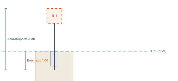
A 0.80 × 0.80 m sign, simplified method, rural clearance 1.50 m. The table gives 1.00 m buried and one column, so the total length is 1.00 + 1.50 + 0.80 = 3.30 m. The dashed blue line is the carriageway, with its level noted at the right.
Two columns
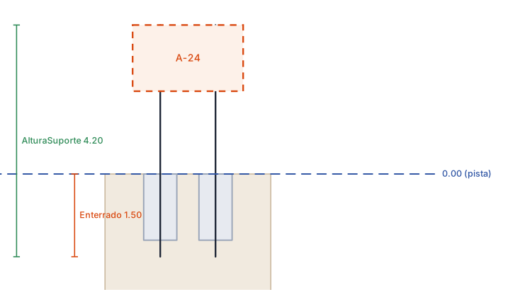
A 2.00 × 1.20 m sign: the table gives 1.50 m buried and two columns, and the total length goes to 4.20 m. The columns sit at ± a quarter of the sign width from the support point, in the direction of the block's rotation.
Rounding and the soil factor
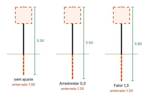
The same 0.80 × 0.80 m sign in three situations. With no adjustment: 3.30 m with 1.00 m buried. With Round 0.5: the total goes up to the next multiple, 3.50 m, and the extra 0.20 m goes below ground (1.20 m buried). With Factor 1.3: the table's buried length becomes 1.30 m and the total 3.60 m.
Terrain and carriageway
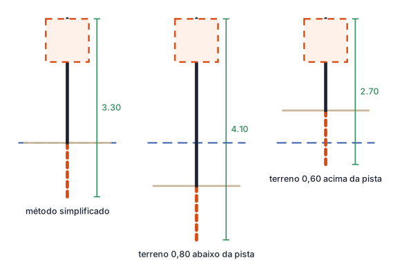
With Include terrain and carriageway, the difference between the carriageway level and the siting point's level enters the sum with its sign. Terrain 0.80 m below the carriageway: the support grows to 4.10 m. Terrain 0.60 m above: it shortens to 2.70 m. In the simplified method that term is zero and the support stays at 3.30 m.
Remembered between sessions
The options of the Support height tab (and of the options tab) live in a single copy while the CAD is open: closing the form saves them and reopening it restores them — including when the reopening comes through the other command. They do not survive closing the CAD: in a new session the values go back to the factory defaults (final message and final report on, section on, length 4, assembly distance 0.2, clearance rural 1.5 / urban 3.0 / MQ-MP-MA 1, embedment from the built-in table with factor 1, foundation included, rectangular, top, simplified method).
The filters of the Manage vertical tab and the list itself are not saved: every opening starts with an empty table, waiting for Process.
Notes
- The list is a snapshot. The filters work on the result of the last Process; if you insert, erase or move signs with the form open, click Process again. The two runs on the Support height tab, by contrast, sweep the drawing there and then.
- The inventory always measures the block definition's geometry; it does not read an AREA attribute. For conventional signs the column comes out zeroed, and it is in the height calculation — not the inventory — that the area and dimension attributes are read.
- The
extcolumn depends on the km attribute. When a sign does not have it filled in, there is an alternative calculation from the project alignment, but it only returns a value for a sign sitting exactly on the alignment; in practice the column stays 0 and the chainage filter cannot reach it. RunCAPCAD_SIGNS_FIX(Vertical Tools) to fill in the chainages before using the range. - One sign per support in the calculation. Each support gets one sign: stacked assemblies are not available in this version. For assemblies, calculate from the lower sign and add the rest by hand. If no sign pairs with the chosen support, it is not processed and the status line records
PlacaDoSuporteNaoEncontrada. - After "Clear filters" (9), the list comes back complete: the conventional signs reappear even with Include conventional off, until another filter changes. Touch any other field — or tick and untick Include conventional — to reapply the filters.
- The section is drawn at real levels. With At 0,0 (24) ticked it can end up a long way from your working area; use Zoom (27) to find it, or leave the box clear and pick a point.
- The plan representation (22) accumulates. Each run adds new circles and the sign line; it does not replace the previous run's drawing. The Reset button (26) erases the section only, not the plan layout.
- Column headings in two languages. The table shows
codigo,area,width,height,ext,açãoandID. - Several status codes and a few dialogs are Portuguese in every language, among them the layer names of the section and the plan layout, and the bracketed status keys (
TerrenoNaoEncontrado,VaoDetectarDeferred,FundacaoCilindricaInfoOnly).