| Command | CAPCAD_MARKING_AXIS |
| Shortcut | none |
| Ribbon | CapCad tab › Manage panel › Analytics split button › Consolidado Visibilidade (Proibições Ultrapassagem) |
| Category | Analytics |
| Form | CapConsolidadoForm — "Consolidated — no-overtaking zones", modal, four tabs plus the Layer control panel. It hides itself while the command asks for selections in the drawing |
| Hosts | AutoCAD, with all four tabs. BricsCAD, GstarCAD, ZWCAD and ARES Commander open the same form, but only the Util tab is available on them |
| Consumes | the layers drawn by CAPCAD_ANALYTICS_HORIZONTAL_OVERTAKING and CAPCAD_ANALYTICS_VERTICAL_OVERTAKING — see Overtaking sight distance |
| Also opened by | nothing |
It gathers everything that prohibits overtaking into a single set of stretches per direction — and then draws the marking. This is the step that closes the loop between the sight-distance analysis and the line that goes to site.
- Plan and profile in the same stretch. The restriction from the horizontal curve and the one from the vertical curve are added along the alignment, not checked one against the other by hand.
- Interval algebra, not drawing. Each curve is projected onto the alignment and becomes a station interval; union, intersection, difference and complement are done on those intervals, so the result never comes out with a leftover or a crooked joint.
- Short permitted stretches disappear. A gap of a few tens of metres between two prohibitions does not become a broken line: a minimum distance merges the two.
- The result lives on the alignment. The consolidated stretches are stored as a property of the alignment itself, not only drawn.
- From zone to marking. The command turns the zones into the three centre-line cases, with the dash cadence, the studs and the no-overtaking signs at the ends.
- A stretch calculator on the side. The Util tab applies any of the operations to curves you select, against the alignment you choose — nothing to do with sight distance.
What it does
The sight-distance commands draw, for each direction, the stretches where overtaking is prohibited — a set of curves on their own layers, usually with a great deal of overlap between the plan analysis and the profile analysis. Consolidated is the next step: it takes those curves, projects each of them onto the alignment (the start and end of each curve become a start and an end station) and resolves the resulting interval algebra.
The union of those intervals is the consolidated prohibition — one stretch per continuous region — drawn back over the alignment and stored in the alignment's properties. With the consolidated prohibition of both directions in hand, the command derives the marking:
- the complement: where nobody is prohibited, the line is broken (overtaking permitted both ways);
- the overlap: where both directions are prohibited, a double continuous line;
- the difference: where only one direction is prohibited, continuous on one side and broken on the other.
The three cases are named on the form after the codes of the Brazilian marking manual — LFO-2, LFO-3 and LFO-4 — and those names go into the layers as well.
The Util tab exposes the same interval operations raw, on curves you select, and the Reports tab gives the lengths in Excel.
What "the alignment" means here. Unlike the rest of CapCad, this command asks for the alignment curve in the drawing on every operation, instead of using the project alignment. Always pick the same entity, or the station intervals will not agree between one run and the next.
Workflow
- Run the sight-distance analyses in both directions — see Overtaking sight distance. They leave the prohibitions on layers
ALIGNMENT_CRES_VISIBILITY_*,ALIGNMENT_DECR_VISIBILITY_*,PROFILE_VISI_RESTR_CRESandPROFILE_VISI_RESTR_DECR. - Run
CAPCAD_MARKING_AXIS. - On the Consolidate tab, leave Gather from the analysis layers (11) ticked, choose the directions (14, 15, 16) and the minimum distance (17, 18).
- Click Consolidate no-overtaking zones (22). The form hides and the command asks for the alignment. At the end, the status line says how many stretches came out in each direction.
- Check the drawing. The Layer control panel turns the analysis and consolidated layers on and off without leaving the form.
- On the Sign tab, choose what to generate and click Sign final (36). The command asks for the alignment again.
- If you want the lengths in a spreadsheet, use the Reports tab.
The form
The numbers below are the same in every capture on this page. The Layer control panel (1 to 10) and the Close button (23) are visible on every tab.
The screenshots are of a Portuguese session, and so are the labels inside the generated figures further down. The layout, the control numbering and the geometry are identical in an English session. The English captions of each control are the ones quoted in the tables.
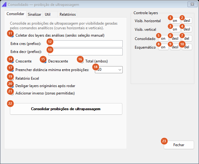
The "Consolidate" tab: merges the analyses' prohibitions into one set per direction.
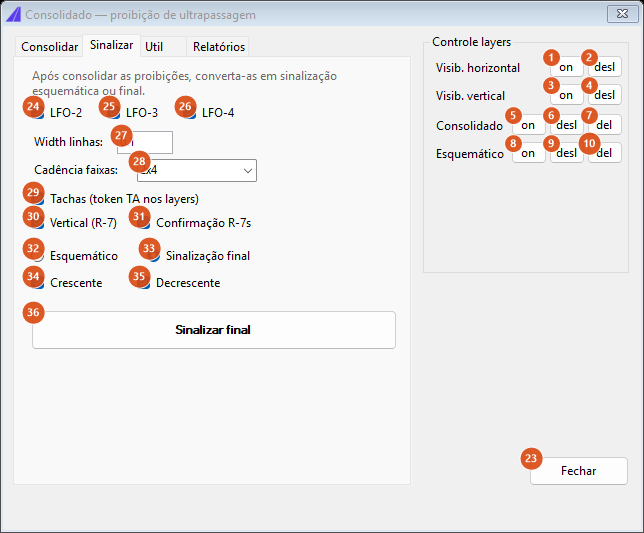
The "Sign" tab: turns the consolidated set into a coloured schematic or into the real marking.
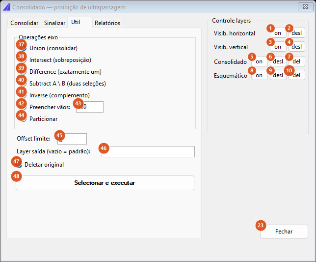
The "Util" tab: the interval operations applied to any selection.
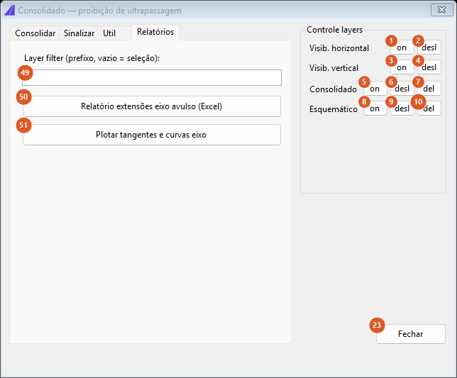
The "Reports" tab: lengths in Excel and a plot of the alignment's tangents and curves.
Consolidate
| # | Control | What it does |
|---|---|---|
| 11 | Gather from the analysis layers (otherwise: manual selection) | On, the command sweeps model space and collects every curve whose layer starts with ALIGNMENT_CRES_VISIBILITY_ or PROFILE_VISI_RESTR_CRES (up-station) and ALIGNMENT_DECR_VISIBILITY_ or PROFILE_VISI_RESTR_DECR (down-station). Off, the command asks for one selection per direction. |
| 12 | Extra incr (prefix): | One more layer prefix, added to the up-station sources. |
| 13 | Extra decr (prefix): | The same, for the down-station ones. |
| 14 | Increasing | Produces PROIBE_CONSOLIDADO_CRES (violet, lineweight 0.60 mm). |
| 15 | Decreasing | Produces PROIBE_CONSOLIDADO_DECR (purple, 0.60 mm). |
| 16 | Total (both) | Produces PROIBE_CONSOLIDADO_TOTAL (red, 0.60 mm) — the union of both directions in one set. With none of the three ticked the command asks you to choose at least one direction. |
| 17 | Fill the minimum distance between zones: | Absorbs gaps shorter than 18: two stretches separated by less than that distance become one. Unticked, the stretches stay as the union produced them. |
| 18 | distance | The minimum distance, in drawing units. Default 120. |
| 19 | Report Excel | Produces a spreadsheet with one row per stretch: direction, start km, end km and length. |
| 20 | Turn the source layers off after running | At the end, turns off the layers the input curves came from, so only the consolidated result stays visible. |
| 21 | Add the inverse (permitted zones) | Also draws the complement — the stretches where overtaking is permitted — on layer CAPCAD_CONSOLIDADO_INVERSE. The basis is Total when it was generated; failing that, the union of the two consolidated directions. |
| 22 | Consolidate no-overtaking zones | Runs. Asks for the alignment, consolidates, draws, stores on the alignment and writes the summary on the status line. |
At the end, the consolidated stretches are stored as properties of the alignment itself — capcad.eixo.proibe.cres.consolidado, …decr… and …both… — so that other commands can read them without depending on the drawing.
Sign
This tab reads back what the previous one drew (PROIBE_CONSOLIDADO_CRES and PROIBE_CONSOLIDADO_DECR). Without them it tells you to run Consolidate first.
| # | Control | What it does |
|---|---|---|
| 24 | LFO-2 | Generates the complement of the union of both directions: where overtaking is permitted. |
| 25 | LFO-3 | Generates the overlap: where both directions are prohibited. |
| 26 | LFO-4 | Generates the two differences: prohibited up-station only, and prohibited down-station only. |
| 32 | Schematic | Draws coloured checking zones only, on four layers: LFO2 (green), LFO3 (red), LFO4-CRES (blue) and LFO4-DECR (orange), all at lineweight 0.60 mm. No road marking is generated. |
| 33 | Final signing | Draws the marking itself, as a linear set: the lines on the layers of the marking-layer grammar, the studs and the no-overtaking signs. |
| 27 | Line width: | The width of the lines generated in the final marking. Default 0.1. |
| 28 | Line cadence: | The cadence of the broken line, in the form AxB (default 2x4: 2 m painted, 4 m gap). Left empty, the command refuses it as invalid. |
| 29 | Studs (TA token in the layers) | Adds the TA token plus the sum of the cadence to the layer name, which makes the command generate the studs as well — with 2x4 the token becomes TA6. |
| 30 | Vertical (R-7) | Inserts the no-overtaking signs at the ends of the zones. The caption names the sign code of the Brazilian catalogue. |
| 31 | R-7 confirmation | Asks before inserting those signs. Answering No, the marking is drawn without them. |
| 34, 35 | Increasing, Decreasing | No effect in this version: both directions are always processed. |
| 36 | Sign final | Runs. When it finishes, it reports how many lines and how many signs were generated and offers to turn off the consolidated layers. |
The definitions used are fixed, assembled from the cadence (28), the width (27) and the studs (29):
| Zone | What is drawn |
|---|---|
permitted both ways (LFO-2) |
one broken line over the alignment, SINA_HOR_AM_<cadence>[TA]_LFO2 |
prohibited both ways (LFO-3) |
two continuous lines, at 0.25 either side of the alignment, SINA_HOR_AM_LFO3, plus the stud line over the alignment (SINA_HOR_AM_TA<n>_LFO3) when 29 is ticked |
prohibited up-station only (LFO-4) |
continuous at +0.25 (SINA_HOR_AM_LFO4) and broken at −0.25 (SINA_HOR_AM_<cadence>[TA]_LFO4) |
| prohibited down-station only | the mirror: broken at +0.25 and continuous at −0.25 |
In an English session the layer that reaches the drawing is written in the English spelling of the same grammar — see Marking Strip for how that grammar is read.
Each one-way zone receives one sign, at one end; the both-ways zones inherit the signs of the neighbouring one-way zones, and a both-ways zone that does not touch the end of any up-station one-way zone gets its own pair, one at each end.
Util
Applies one interval operation to curves you select, against the alignment you choose. It has nothing to do with sight distance: it works for any set of stretches along an alignment.
| # | Control | Operation | Default layer · colour |
|---|---|---|---|
| 37 | Union (consolidate) | merges the stretches that touch or overlap; with 43 filled in, also absorbs gaps shorter than it | PROIBE_CONSOLIDADO · 1 |
| 38 | Intersect (overlap) | the stretches covered by two or more curves of the selection | LFO-3 · 6 |
| 39 | Difference (exactly one) | the stretches covered by exactly one curve | LFO-4 · 2 |
| 40 | Subtract A \ B (two selections) | asks for two selections: what is left of the first after removing the second | CONSOLIDADO_SUBTRACT · 4 |
| 41 | Inverse (complement) | what is not covered, from the start to the end of the alignment | CAPCAD_CONSOLIDADO_INVERSE · 92 |
| 42, 43 | Fill gaps: | returns only the gaps shorter than the value — the missing pieces, not the merged set | PROIBE_CONSOLIDADO_GAPS · 30 |
| 44 | Partitionate | cuts the stretches at the ends of every stretch in the selection | CONSOLIDADO_PARTITION · 8 |
| # | Control | What it does |
|---|---|---|
| 45 | Offset limit: | Discards curves whose end lies farther than this perpendicular distance from the alignment — a curve that does not belong to this alignment. 0 accepts everything. |
| 46 | Output layer (empty = default): | The result's layer. Left empty, it uses the operation's default layer from the table above. |
| 47 | Delete original | Erases the selected curves after producing the result. |
| 48 | Select and run | Runs. Asks for the alignment and then for the selection (two, in Subtract). If nothing is produced, it says so and asks you to check the selection and the alignment. |
Reports
| # | Control | What it does |
|---|---|---|
| 49 | Layer filter (prefix, empty = selection): | A layer prefix. Filled in, the report uses every curve on those layers; empty, the command asks for a selection. |
| 50 | Standalone alignment lengths report (Excel) | Asks for the alignment, projects the curves onto it and opens a spreadsheet with the start km, end km and length of each stretch. |
| 51 | Plot the alignment's tangents and curves | Redraws the alignment split by segment type: EIXO_TANGENTES (grey), EIXO_CURVAS_DIR (red) and EIXO_CURVAS_ESQ (blue), all at lineweight 0.50 mm — a visual check of where the right-hand and left-hand curves are. |
Layer control
Turns whole families of layers on, off and out, by prefix, without leaving the form.
| # | Control | Acts on |
|---|---|---|
| 1, 2 | Horizontal sight — on / off | ALIGNMENT_CRES_VISIBILITY_* and ALIGNMENT_DECR_VISIBILITY_* |
| 3, 4 | Vertical sight — on / off | PROFILE_VISI_RESTR_CRES* and PROFILE_VISI_RESTR_DECR* |
| 5, 6, 7 | Consolidated — on / off / del | PROIBE_CONSOLIDADO_CRES*, …DECR*, …TOTAL* and CAPCAD_CONSOLIDADO_INVERSE* |
| 8, 9, 10 | Schematic — on / off / del | LFO2*, LFO3*, LFO4-CRES* and LFO4-DECR* |
| 23 | Close | Closes the form. |
del erases the entities on those layers in model space, without confirmation.
How the operations combine
The figures below were produced by running the command's own engine on a straight 3000-unit alignment. The bars are the stretches, at the station where they fall; the scale underneath is the length along the alignment. Their labels are from a Portuguese run.
Consolidate
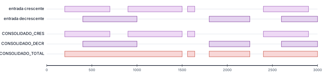
Four up-station prohibitions and three down-station ones go in; three sets come out. CONSOLIDADO_CRES and CONSOLIDADO_DECR are the union within each direction; CONSOLIDADO_TOTAL is the union of both — note that it merges 200–700 with 400–1000 into a single stretch, 200 to 1500.
Filling the minimum distance

The same up-station set, without and with the 120 fill: the 60-unit gap between 1500 and 1560 disappears and the two stretches become one, 900 to 1640. The 760-unit gap between 1640 and 2400 stays.
From the two directions to the three marking cases
From the two consolidated sets, the three cases are pure set algebra over the alignment:
| Case | Definition |
|---|---|
| permitted both ways | the complement of the union of the two directions |
| prohibited both ways | the intersection of the two directions |
| prohibited one way only | each direction minus the other, giving two zones |
The four resulting bands cover the whole alignment, with no gap and no overlap.
The figure that shows this on the Portuguese page is labelled with the marking codes of the Brazilian manual, so it is not reproduced here.
The Util tab's operations
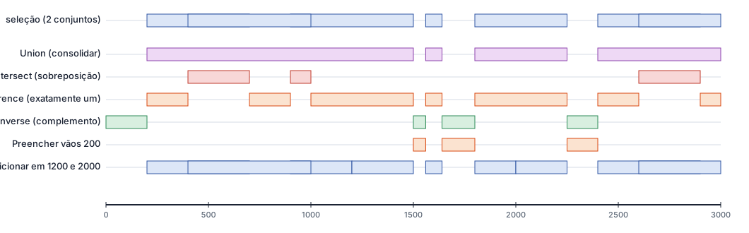
One selection holding both sets, and what each operation returns. Note two easily confused differences: Fill gaps returns only the gaps, not the merged set; and Partitionate does not change the coverage, it only cuts the stretches at each other's ends — 900–1500 becomes 900–1200 and 1200–1500.
Remembered between sessions
Nothing. This form does not keep your choices: every run starts from the defaults — gather from the layers on, increasing and decreasing ticked, fill 120, cadence 2x4, width 0.1, final signing.
Notes
- The projection uses only the ends of each curve. The first and last vertex of each entity are projected onto the alignment; what the curve does between them does not count. An analysis curve that doubles back is read as the whole interval between its ends.
- A curve that does not project is discarded silently, as is one that collapses to a point. If the result comes out smaller than expected, check that the input curves are near the chosen alignment, or use Offset limit (45) to make the rejection explicit.
- The command asks for the alignment on every operation. Consolidate, Sign, Util and both reports all ask for the reference curve again. Picking different entities between runs shifts the stations.
- Running Consolidate twice accumulates drawing. The previous stretches on the
PROIBE_CONSOLIDADO_*layers are not erased. Use del (7) on the layer panel before redoing it. Consolidatestores on the alignment;Signdoes not. The final marking reads the drawing, not the stored properties.- The cadence recommended by the criteria is not available in this version. The cadence is whatever you type in 28.
- Some captions carry the Brazilian marking and sign codes: the three case check boxes (24, 25, 26), the sign check box (30) and the schematic layer names. They are the literal captions and layer names of this version.
- The Util tab's operation names are in English on every language, and the Line width label on the Sign tab mixes two languages.
- For the analyses that feed this command, see Overtaking sight distance and critical grades. For the classification of the curves and the warning signs, see Curve Utilities.