This page covers the commands that work on surface marking that is already drawn — rather than drawing new marking — and the window that gathers the horizontal commands.
| Commands | CAPCAD_MARKING_SPACING_MATCH (match spacing) · CAPCAD_MARKING_SPACING_RENDER (render strip) · CAPCAD_MARKING_SPACING_RENDER_3D (the same form, entered from the 3D side) · CAPCAD_MARKING_HUB (horizontal hub) |
| Shortcuts | AE (match spacing) · SHMAN (hub). The other two have none |
| Ribbon | CapCad tab › Horizontal panel › Faixas split button › Ajusta Espaçamento and Plotar Faixa. CAPCAD_MARKING_SPACING_RENDER_3D sits on the BIM panel › 3D split button › Horizontal 3D Tools. CAPCAD_MARKING_HUB has no ribbon button |
| Category | CAPCAD_MARKING_SPACING_MATCH and CAPCAD_MARKING_SPACING_RENDER: Horizontal · CAPCAD_MARKING_SPACING_RENDER_3D and CAPCAD_MARKING_HUB: none |
| Forms | GeometryTransformForm "Geometry Transform", tabs Main, Info and Tutorial, modeless · HorizontalHubForm "Sinalização horizontal", modeless. CAPCAD_MARKING_SPACING_MATCH has no form: it works on the command line |
| Hosts | AutoCAD. On ARES Commander the first three exist and report that they are not available yet; not available on BricsCAD, GstarCAD and ZWCAD. The hub is AutoCAD only |
| Also opened by | none |
A broken line that ends in the middle of a gap is a mistake that shows up on site, and no CAD command fixes it. Here you point at the line and it shrinks or grows by whole patterns, without moving the end you care about.
- The end you clicked stays put. The adjustment always moves the other one.
- C and D until it is right. After the first fit,
Cgrows andDshrinks by one mark + gap at a time, as often as you like. - The cadence comes from the line itself. Mark and gap come from the entity's linetype, resolved through the layer when it is ByLayer, already multiplied by the linetype scale.
- Render strip turns cadence into geometry. The dashed line becomes closed boundaries, widthed polylines or regions — whatever the construction drawing asks for.
- The hub gathers the horizontal commands into one window, with a rail on the left and the command's panel on the right.
What it does
CAPCAD_MARKING_SPACING_MATCH — match spacing
You select a cadenced line. The command reads its linetype's mark and gap — resolving through the layer when the object is ByLayer, and multiplying both by the entity's linetype scale — and recomputes the length to the nearest multiple of the mark + gap pattern, so the line ends on a whole mark.
The end that stays put is the one nearest the point you clicked; the other one moves. The line is replaced by a new one of the adjusted length.
The command then keeps asking: C grows by one pattern, D shrinks by one pattern, any other key ends it. If the fit would change nothing, the command pushes one pattern outwards, so C always really grows.
If the entity has no dashed linetype, it reports "No spacing pattern found - nothing changed" and touches nothing.
CAPCAD_MARKING_SPACING_RENDER — render strip
The opposite: it takes lines that represent a cadence (one line, with a layer that states the cadence, or with mark and gap typed in) and draws the geometry that cadence implies — each mark as a closed boundary, or as a widthed polyline, or as boundaries to become regions.
This is what you do before plotting, measuring area or exporting: the drawing stops depending on the linetype.
CAPCAD_MARKING_SPACING_RENDER_3D opens exactly the same form. The 3D options live in it; the Surface (LandXML) option asks for a LandXML file at run time.
CAPCAD_MARKING_HUB — the horizontal hub
A window with a rail of commands on the left and the selected command's panel on the right. Each rail item opens the panel of the standalone command, and the licence is checked item by item, exactly as the standalone command would.
The rail carries one item in this version, in the Zebrado group: Zebrado 1 lado (the one-side chevron). Every other command stays reachable through its own command, and every command the hub lists goes on working on its own.
A docked panel that needs to hide itself for a pick in the drawing hides the whole hub, not just the panel; and closing the hub closes each docked form, so that each one's live preview is cleared from the drawing.
Workflow
Match spacing
- Run
CAPCAD_MARKING_SPACING_MATCH(or typeAE). - Click the line, near the end that should stay put.
- The line is adjusted at once.
- Type
Cto grow one pattern,Dto shrink one, or any other key to leave.
Render strip
- Run
CAPCAD_MARKING_SPACING_RENDER. - Choose how the cadence is obtained (11 or 12) and the width (1 or 2).
- Choose the output (4, 7, 10) and its options.
- Click Select (23) and select the lines.
- The result is drawn; with Delete input (17) ticked the original lines disappear. Elements with no usable cadence are listed in a box at the end.
The form
The numbers below are those of the Geometry Transform form. The Info and Tutorial tabs carry only text and the video link, plus the presets combo (28), which appears on all of them.
The screenshots below were captured in a Portuguese session; the control numbering is the same in every language, and the tables quote the English captions the form shows in an English session.
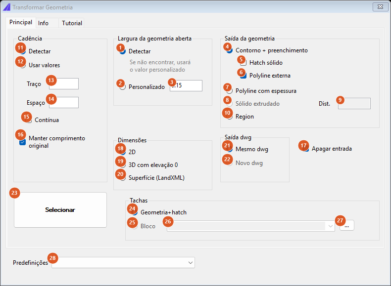
The Main tab. The greyed-out controls are not available in this version, and their tooltip says so.
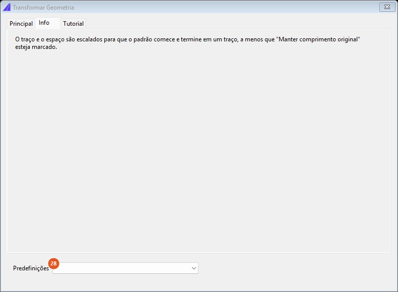
The Info tab: the note on how mark and space are scaled so that the pattern starts and ends whole.
Cadence
| # | Control | What it does |
|---|---|---|
| 11 | Detect | Mark and space are read from the entity's layer name. This is the default. |
| 12 | Use values | Mark and space are the ones typed in 13 and 14. |
| 13 | Mark | The mark length. |
| 14 | Gap | The gap length. |
| 15 | Continuous | No cadence: the whole line becomes a single mark. It overrides 13 and 14. |
| 16 | Keep original length | Does not rescale the pattern to end on a whole mark: keeps the length as it is. Ticked by default. |
Open geometry width
| # | Control | What it does |
|---|---|---|
| 1 | Detect | The width comes from the layer. If none is found, the custom value is used — as the text under the button says. |
| 2 | Custom | Always uses the value in 3. |
| 3 | (value) | The width, in metres. Default 0.15. |
Geometry output
| # | Control | What it does |
|---|---|---|
| 4 | Boundary + filling | Each mark becomes a closed boundary. This is the default. |
| 5 | Solid hatch | Asks the CAD for a solid hatch inside each boundary. |
| 6 | Outer polyline | Also draws the outer polyline of each boundary. Ticked by default. |
| 7 | Widthed Polyline | Each mark becomes a polyline of constant width, instead of a boundary. |
| 8 | Extruded solid | Disabled; not available in this version. |
| 9 | Dist. | The extrusion height for 8; disabled along with it. |
| 10 | Region | Draws the boundaries and then converts them into regions, erasing the polylines. A boundary the CAD will not accept as a region is left as it is. |
Dimensions and dwg output
| # | Control | What it does |
|---|---|---|
| 18 | 2D | The normal path, and the default. |
| 19 | 3D with 0 elevation | The strips are swept in 3D at elevation zero. |
| 20 | Surface (LandXML) | The same, draped over a surface: the command asks for a LandXML file before running. When it finishes, it reports how many strips, devices and areas were converted. |
| 21 | Same dwg | The output goes to the current drawing. This is the default. |
| 22 | New dwg | Disabled; not available in this version. Ticking it also clears and disables Delete input. |
| 17 | Delete input | Erases the selected entities after drawing. Ticked by default. |
Studs, selection and presets
| # | Control | What it does |
|---|---|---|
| 24 | Geometry+hatch | Studs come out as drawn geometry. This is the default. |
| 25 | Block | Disabled; not available in this version. |
| 26 | (block name) | The list comes from the .dwg files in the project library's ITEMS_AVULSOS folder. Disabled along with 25. |
| 27 | … | Opens the project library's ITEMS_AVULSOS folder in the file explorer, creating it if it does not exist. |
| 23 | Select | Hides the form, asks for the selection and runs. At the end it writes to the command line how many entities were drawn, and shows in a box the list of those that could not be converted. |
| 28 | Presets | The list exists — Civil 3D surface, 3D at elevation 0, new file, 2D, new file — but is not available in this version: picking one changes no control. |
How the options combine
The figures below came out of the engines themselves.
Match spacing
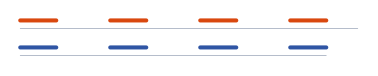
A 4/6 strip 37.5 m long (orange, above) ends in the middle of a gap. Fitted, it becomes 34 m (blue, below) and ends on a whole mark. C would take it to 44, D to 24.
Render strip

A 30 m line with cadence 4/6 and width 0.15, output Boundary + filling: each mark becomes a closed rectangle.

The same line with output Widthed Polyline: the same marks, now as polylines of constant width 0.15.
Remembered between sessions
None of the four commands keeps preferences. The Geometry Transform form is a per-session singleton: reopening it brings back the window as you left it, but closing the drawing resets everything.
Notes
CAPCAD_MARKING_SPACING_MATCHreplaces the entity: the original is erased and a new one is created with the adjusted length. The command copies nothing but the geometry, so check the layer and linetype if the result comes out different.- The fit always starts from the current line, so a run of
Cgrows cumulatively. CAPCAD_MARKING_SPACING_RENDER_3Ddoes not preselect the 3D options on the form: it opens the same window and you choose the dimension in 19 or 20. The 3D options are live; what is disabled is the extruded solid, the new-drawing output and the stud-as-block mode.CAPCAD_MARKING_HUBhas no ribbon button; no command depends on it.- Because the hub opens a command's panel without going through the command, the licence check is repeated per rail item; if the licence is refused, the hub simply stays on the previous panel.
- The hub's window title and the Cadência and Tachas group boxes on the Geometry Transform form are shown in Portuguese in every language.