| Command | CAPCAD_ALIGNMENT_CHAINAGE |
| Shortcut | — |
| Ribbon | CapCad tab › Manage panel › Alignments split button › Eixo Tools |
| Category | Manage: Alignment |
| Form | CapAlignmentToolsForm — Alignment Tools, modeless, one instance (running the command again brings the open form to the front) |
| Hosts | AutoCAD, BricsCAD, GstarCAD, ZWCAD, ARES Commander |
| Also opened by | The More chainage options button on the Actions tab of the Alignment Manager |
| Related command | CAPCAD_ALIGNMENT_TOOLS — despite the name it does not open this form: it opens the Alignment Manager on the Actions tab |
The Manager's chainage is fixed at 20/100; here you own the intervals, the format and the offset — and you can unfold the road into a unifilar diagram. This is the fine-work form of the alignment: chainage the way the project asks for it, undo a chainage run with one click, and turn kerbs, fences and roadside blocks into a linear diagram.
- Chainage to measure. Free major and minor intervals, initial station, length factor and perpendicular offset; the label format comes from a list, and the field also accepts a mask you type.
- Undo is one click. Every chainage run tags the blocks it inserts with its own group id, and Reset erases exactly that run — not the station marks that were already in the drawing.
- Works on the project alignment or on any polyline. The Alignment box switches between the active alignment and a curve you pick on the spot, with no project needed.
- A real unifilar. What is drawn in plan becomes (station, offset) coordinates: curves are straightened, blocks are moved and un-rotated, and every entity comes out on the layer of the entity it came from.
- A conversion report. Every converted entity appears in an original → conversion table, with the handles, so you can check what went in and what stayed out.
- Alignment and profile on one screen. Two buttons split the model into two viewports (alignment above, profile below) and interlocate points between them.
What it does
The form gathers the operations that work on an alignment that already exists and do not fit in the Alignment Manager: chainage with free parameters, and building the unifilar — the schematic view in which everything around the road is rewritten in (station, offset) coordinates, as if the road were a straight line.
There are four tabs, and the last two are empty:
| Tab | What it is for |
|---|---|
| Unifilar | Convert drawing entities into the unifilar diagram, draw the straightened alignment, arrange alignment and profile on screen. |
| Chainage | Insert the station marks with the intervals, initial station, factor, offset and format you choose. |
| Right of way | Empty. Right-of-way strips live on the tab of the same name in the Alignment Manager. |
| Annotations | Empty. PC/PT and radius annotations live on the Actions tab of the Alignment Manager. |
The Alignment box at the bottom is shared by all four tabs and decides what the two useful tabs work on.
Workflow
- Run
CAPCAD_ALIGNMENT_CHAINAGE. The form opens modeless; you keep working in the drawing with it open. - Check the Alignment box at the bottom. With an active alignment in the drawing, Project (1) is already selected; without one it turns green and disabled and Select (2) takes over. The ⟳ (3) re-reads the drawing after you define an alignment in the Manager.
- On the Chainage tab, set the Major station interval (24, the numbered one) and the Minor station interval (25, the unnumbered one). The major must be a whole multiple of the minor.
- Choose the Station format (27).
- Click ok (35). With Select ticked, CapCad asks for the curve to chainage and uses the Initial station value (26) and the Factor (30) you typed.
- Not happy? Reset (32) erases the whole last run.
- For the unifilar, go to the Unifilar tab, set the Limit (5) and the Arc precision (7), click the big button (4), point at the reference and select the entities. The conversion table opens at the end.
The form
Numbers are the same in every screenshot of this page. The Alignment box at the bottom appears on every tab and keeps numbers 1 to 3; the Unifilar tab runs from 4 to 23 and the Chainage tab from 24 to 35. The labels Limit, Arc precision, (numbered), (not numbered) and multiply station values are not clickable and get no number.
The screenshots are the Portuguese renders of the form; the control positions are identical in every language.
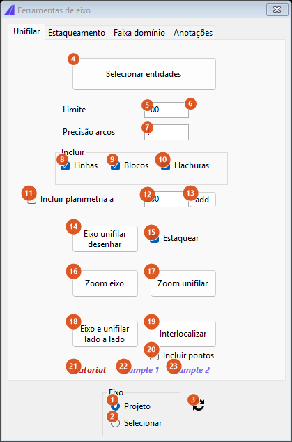
Unifilar tab with Project selected: the conversion button reads "Select entities", because the reference comes from the project alignment itself.
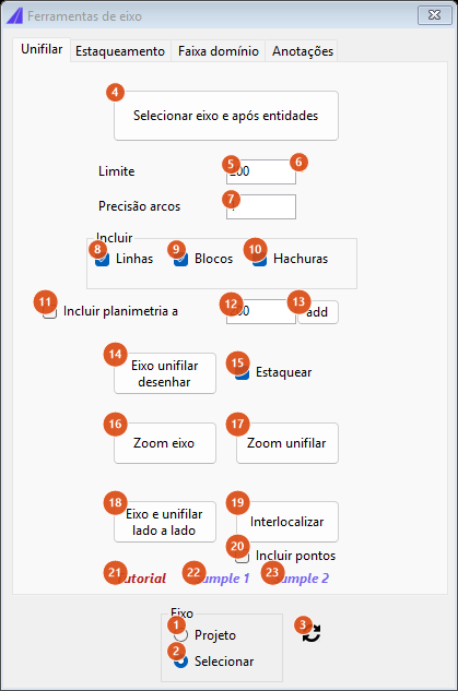
The same tab with Select ticked: the button becomes "Select alignment then entities" — the reference is a curve you pick.
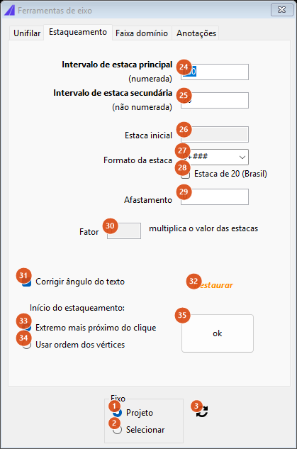
Chainage tab on the project alignment: Initial station value (26) and Factor (30) are greyed and read-only, because those values come from the alignment itself. In Select mode both become editable.
Alignment box (shared by every tab)
| # | Control | What it does |
|---|---|---|
| 1 | Project | Use the drawing's active alignment. When the drawing has none, this option is green and disabled and Select is ticked instead; when it has one, it is blue, enabled and already ticked. In this mode Initial station value (26) and Factor (30) are read-only: the values come from each segment. |
| 2 | Select | Work on a curve picked in the drawing on the spot (line, polyline or arc). Anything else is refused with Deve ser uma linha, polilinha ou arco. In this mode Initial station value and Factor count, and are what you typed. |
| 3 | ⟳ | Re-read the drawing: if an active alignment now exists, (1) goes back to blue, enabled and ticked. Use it after defining an alignment in the Manager with this form already open. |
Tab 1: Unifilar
| # | Control | What it does |
|---|---|---|
| 4 | Select entities / Select alignment then entities | Runs the unifilar conversion. Needs a project alignment defined in either mode. With Select (2) it asks for the reference curve first; with Project (1) it uses one segment of the active alignment — if the alignment has more than one, the command line asks Segmento do eixo (1-N). Then you select the entities to convert. Each curve is rewritten with X = station and Y = signed offset — and the sign is inverted, so that what lies to the left of the walking direction comes out below the unifilar alignment line — and drawn on the layer of the source entity; each block is copied to the projected position and rotated back by the alignment's tangent angle, ending up horizontal. Hatches come in through their boundaries, and only when the boundary is a polyline. At the end the Unifilar window opens with one line per entity: source handle → generated handles, Não desenhado for what stayed out, and the suffix particionado when the entity came out broken into more than one piece. Nothing convertible: Nada convertido. |
| 5 | Limit | Maximum offset, in drawing units, for an entity to be converted (default 200). A vertex beyond the limit breaks the output at that point: the piece so far is drawn, and the conversion restarts at the next vertex that fits. |
| 6 | ? | Shows the reminder Entidades que ultrapassarem o limite de distância de offset em algum ponto, não serão incluidas. |
| 7 | Arc precision | Chord length, in drawing units, at which arcs are discretised before projection (default 1). The smaller it is, the more faithful the curvature is in the unifilar; 0 switches discretisation off and an arc becomes a straight line between its two ends. |
| 8 | Lines | Not used by this version: ticked or not, curves are always converted. |
| 9 | Blocks | Not used by this version: ticked or not, blocks are always converted. |
| 10 | Hatches | Not used by this version: ticked or not, hatch boundaries are always converted. |
| 11 | Include planimetry at | After the conversion, also draws the planimetry (the plan strip of the profile chart) with the clearance of (12). Only the planimetry: the grid is not drawn. |
| 12 | (clearance box) | Clearance, in drawing units, used by the planimetry of (11) and by the add button (13). Default 200. |
| 13 | add | Draws the planimetry on its own, without running the unifilar conversion, with the clearance of (12). |
| 14 | Draw unifilar alignment | Draws the straightened alignment: one line per segment, from its initial to its final station, at y = 0, on the segment's own layer. It is the ruler the rest of the unifilar rests on. |
| 15 | Station | With (14): also chainages the straightened alignment, every 20 with a label every 100, using the Station/km format stored on each source segment. The marks go to the CAPCAD_STATION layer. |
| 16 | Zoom alignment | Frames the active alignment. Same effect as CAPCAD_ALIGNMENT_ZOOM — see Navigating the alignment. |
| 17 | Zoom unifilar | Frames the computed straightened alignment, not the drawn copy: it works even before you click (14). |
| 18 | Side by side | Splits the model into two viewports side by side, one framing the alignment and the other the profile. Same effect as CAPCAD_ALIGNMENT_PROFILE_ZOOM; with the model already split in two, the button goes back to a single viewport. Needs an alignment and a profile, otherwise Necessário tanto eixo como perfil definidos para este comando. |
| 19 | Interlocate | With the model split into two viewports, every point you click is located in the other one: click in plan and the other viewport goes to the matching station of the profile, and the other way round. Same effect as CAPCAD_ALIGNMENT_PROFILE_INTERLOCATE. |
| 20 | Include points | With (19): marks each pair with an X on both sides, a different colour per click, and asks at the end whether you want to keep the drawn points. Unticked, (19) only navigates. It is the difference between CAPCAD_ALIGNMENT_PROFILE_POINT and CAPCAD_ALIGNMENT_PROFILE_INTERLOCATE. |
| 21 | Tutorial | Opens the unifilar video on YouTube. |
| 22 | Sample 1 | Downloads the sample drawing sample-unifilar.dwg from the CapServer, opens it in a new document and makes the sample alignment sample-unifilar.capcad current. |
| 23 | Sample 2 | The same with sample-unifilar-2. |
Tab 2: Chainage
| # | Control | What it does |
|---|---|---|
| 24 | Major station interval (numbered) | Distance, in station units, between the marks that get a label. Default 100. |
| 25 | Minor station interval (not numbered) | Distance between the unlabelled marks. Default 20. Left at 0, the major value is used. |
| 26 | Initial station value | Station value of the first vertex of the selected curve. Only counts in Select mode (2); in Project mode it is greyed, because every segment already carries its own. |
| 27 | Station format | Mask of the major label. The list offers 0, 0m, 0.00, 0+000 and 0+###.0, and the field also accepts text you type; the factory default is 0+###. Left empty, 0 is used. Only 0+000 (and its decimal variants) produce the kilometre+metres notation; the others produce a plain number. |
| 28 | Estaca de 20 (Brazil) | Only shown in the Brazilian country profile. In every other profile the control is invisible and never taken into account, and the chainage always uses the format of field (27). Its behaviour is documented on the Portuguese edition of this page. |
| 29 | Offset | Perpendicular offset of each mark from the alignment, in drawing units. Positive shifts to the left of the walking direction. Careful: this same box is read by the unifilar conversion of the other tab, as an offset added to every converted entity. |
| 30 | Factor | Length factor of the selected curve — multiplies the distance travelled to reach the station value. Only counts in Select mode (2). |
| 31 | Correct angle text | Not used by this version. |
| 32 | Reset | Erases the last chainage run made by this form. Each run tags every block it inserted with its own group id, and it is that id the button looks for: marks from another run, or from the Alignment Manager, are not touched. After resetting once, the button has nothing left to erase until the next run. |
| 33 | Closest end to clicked point | Not used by this version. |
| 34 | Use vertices order | Not used by this version. |
| 35 | ok | Runs the chainage. If the minor interval is zero, the major is used; if both are zero, it refuses with Valores inválidos. If the major is not a whole multiple of the minor, it refuses with the note Chainage minor and major values must be multiple (ex 100 / 4 = 25). In Project mode it chainages the whole active alignment; in Select mode it asks for the curve (Selecione o eixo a estaquear) and applies the factor (30) and the initial station (26) to it. The STATION blocks go to the CAPCAD_STATION layer. |
How the options combine
The figures below come from the same chainage and unifilar engines the form calls, run on a sample alignment 137 units long with initial station 11 990.
Chainage
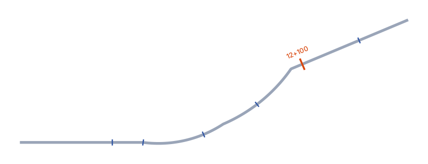
Major interval 100 and minor 20, format 0+000: six marks, one every 20 station units, and a single label — 12+100 — on the multiple of 100. The minor marks come in without text.
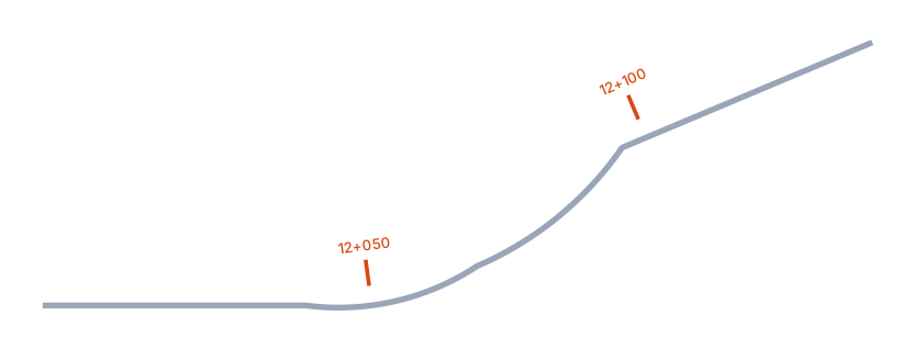
Major and minor both 50, with offset 5: every mark is a major one and gets a label (12+050, 12+100), and all of them are shifted 5 units to the left of the walking direction.
Unifilar
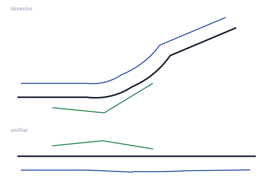
Above, the drawing: the alignment (black), a kerb on the left (blue) and a fence crossing from one side to the other (green). Below, the same set after conversion: the alignment becomes a horizontal straight line, the kerb — which lies to the left of the walking direction — comes out below it at a nearly constant offset, and the fence appears as the curve of its offset from the alignment, crossing the line where it crosses the road in the drawing.
Remembered between sessions
Nothing. This form saves no preferences: intervals, format, limit, precision and check boxes go back to the factory values every time it opens. What does survive within the session is the id of the last chainage run, used by Reset (32).
Notes
CAPCAD_ALIGNMENT_TOOLSdoes not open this form. Despite the name, it opens the Alignment Manager on the Actions tab. The command that opens Alignment Tools isCAPCAD_ALIGNMENT_CHAINAGE.- The Offset (29) is shared by both tabs: a value left there for the chainage also shifts everything the unifilar conversion produces. Zero it before converting if that is not what you want.
- Five controls are not used by this version and are marked as such in the tables: Lines (8), Blocks (9), Hatches (10), Correct angle text (31) and the Chainage start pair (33, 34).
- The straightened alignment that Draw unifilar alignment (14) produces comes out with factor 1 and the initial station of its source segment, precisely so that Station (15) can mark it.
- The tab caption Unifilar, the two prompts (Segmento do eixo, Selecione o eixo a estaquear), the conversion-report words (Não desenhado,
particionado, Nada convertido), the refusals (Deve ser uma linha, polilinha ou arco., Valores inválidos, Necessário tanto eixo como perfil definidos para este comando.) and the hint behind (6) stay Portuguese in every language; they are quoted here as the software prints them. - Hatches are only converted through boundaries that are polylines; a boundary built from arc or spline edges is ignored silently and the entity comes out as Não desenhado.
- The Right of way and Annotations tabs are empty. Both functions exist, but in the Alignment Manager.
See also
- Alignment Manager — create the alignment, its segments and the standard 20/100 chainage.
- Alignment properties — the per-station values the alignment carries.
- Draw and edit the alignment — draw the alignment, auxiliary alignments, identify a segment and clean the road.
- Navigating the alignment — zoom, alignment and profile side by side, interlocation and driving the stretch.
- Station Navigator — go to a station and identify a point.