| Commands | CAPCAD_SIGN_ASSEMBLY and CAPCAD_SIGN_ASSEMBLY_OPTIONS (sign in an assembly) · CAPCAD_SIGN_SET_PLACE (sign sets along the alignment) |
| Shortcuts | CJ (CAPCAD_SIGN_ASSEMBLY). The other two have none |
| Ribbon | CapCad tab › Sinalização Vertical panel › Conjunto Vertical button (runs CAPCAD_SIGN_SET_PLACE). The two assembly commands have no button |
| Category | Vertical (all three commands) |
| Form | CAPCAD_SIGN_ASSEMBLY and _OPTIONS: none, everything on the command line. CAPCAD_SIGN_SET_PLACE: VerticalSetsForm ("Conjunto Vertical") or VerticalSet2Form ("Conjuntos de placas"), both modeless |
| Hosts | AutoCAD. On ARES Commander all three commands exist but answer "is not yet available in ARES (coming soon)"; on BricsCAD, GstarCAD and ZWCAD they are not available in this version |
| Also used by | Swap and substitute, which builds the "new implanted + old removed" assembly in the same way, and the in an existing assembly method of sign insertion |
Two signs on one post are not two loose insertions: they are an assembly, and CapCad builds the second one from the first. Copying and moving the block by hand gets the height wrong, loses the station and leaves the quantities unaware that the two share a post.
- The height is measured, not guessed. CapCad measures the reference sign and puts the new one exactly above it (or below), with the gap you asked for.
- The right side by itself. Told nothing, the command works out which side the post is on and grows the assembly the other way.
- A line joins the two. The connecting line is drawn on the layer of the action of the sign it represents, and it is what Fix Traffic Signs sees when it treats the two signs as one assembly.
- The new sign inherits what matters. Station, latitude, longitude, scale and the EXTRA attribute come from the reference sign; the rest is derived at insertion.
- Sets along the alignment. The sign-set command places entry/exit pairs on a curve, or one sign every N metres along a stretch, straight onto the project alignment.
- Ready-made speed-reduction chains. Also in the sign-set command, a staged speed-reduction method builds the sequence of speed-limit signs up to the critical point, at one point or along the whole alignment at once.
What it does
An assembly is a group of signs sharing one post: one above the other (sometimes side by side), joined by a line. It is the commonest arrangement on a highway — a regulatory sign with a warning sign, or a main sign with its supplementary plate.
CapCad builds an assembly the same way every time: you point at a sign already in the drawing (the reference sign) and say which code joins it. The command then
- measures the reference sign (the block height times its effective scale);
- decides the side, either because you said so, or by looking at which side the post is on;
- places the new sign at height + gap away, at the same rotation as the reference;
- draws the connecting line between the reference and the new sign, on the action's layer.
The new sign inherits from the reference the station, the latitude, the longitude, the scale and the EXTRA attribute, and is inserted the same way as in sign insertion, which derives the code, area, dimensions, layer and graphic style on its own.
Two commands do exactly that from the command line:
CAPCAD_SIGN_ASSEMBLY(CJ) — asks only for the code and for the reference sign; uses the automatic gap and works out the side by itself.CAPCAD_SIGN_ASSEMBLY_OPTIONS— also asks for the side (left, right, above, below) and the distance between the signs.
The same mechanism is used by Swap and substitute: the old sign comes back into the drawing as the assembly's second sign, with the remove action.
The gap between the signs
The gap is the clear space between the top of the reference sign and the bottom of the new one.
| How you ask | Gap applied |
|---|---|
CAPCAD_SIGN_ASSEMBLY (automatic) |
5 units — or 15 under one Brazilian paradigm |
CAPCAD_SIGN_ASSEMBLY_OPTIONS, typed value |
the typed value (10 is offered as the default) |
CAPCAD_SIGN_ASSEMBLY_OPTIONS, value 0 |
0.001 — a typed zero does not fall back to the automatic gap, it becomes a practically null gap |
The sign-set command is a different thing
CAPCAD_SIGN_SET_PLACE, the Conjunto Vertical ribbon button, does not despite its name stack signs on a post: it works along the alignment. It is a fork, decided the moment it opens:
- under the Brazilian country profile the command asks "Selecione: Sim = Distância reserva, Não = Placas agrupadas" (Yes = reserve distance, No = grouped signs);
- Yes opens the Conjunto Vertical form, with the Conjuntos page (curve sign pairs, or one sign every N metres) and the Mudanças velocidade page (the staged speed-reduction chain);
- No — and also every non-Brazilian country profile, which never sees the question at all — opens the Conjuntos de placas form, the inserter for alignment markers (delineators, chevrons) on a curve or along a stretch.
So under any other country profile this command goes straight to the second form. The Conjunto Vertical form documented below is only reachable under the Brazilian profile; it is described here for completeness, and its tables live on the Portuguese edition of this page.
Workflow
Stacking a sign (CJ)
- Run
CJ(orCAPCAD_SIGN_ASSEMBLY). - Answer Placa a ser inserida num conjunto: (sign to insert into an assembly) with the code. Enter on an empty line cancels.
- Answer Selecione a placa de referência: (select the reference sign) by clicking the sign already in the drawing.
- The command line confirms Placa inserida no conjunto (sign inserted into the assembly) — or Não foi possível inserir a placa no conjunto, when the code could not be inserted (for example a code that exists neither in the library nor as a generic fallback sign).
Stacking with a chosen side and gap (CAPCAD_SIGN_ASSEMBLY_OPTIONS)
- Run
CAPCAD_SIGN_ASSEMBLY_OPTIONS. - Give the code.
- Choose the side keyword: Esquerda (left), Direita (right), Superior (above) or Inferior (below). Enter without choosing ends the command.
- Give the Distancia excedente — the gap. Enter accepts the default of 10.
- Click the reference sign.
On the left and right sides the command draws no connecting line: the two signs sit side by side, with no connector.
Sign sets: alignment markers on a curve or a stretch
- Run
CAPCAD_SIGN_SET_PLACE. Under a non-Brazilian profile the Conjuntos de placas form opens directly; under the Brazilian one, answer No to the question. - Choose the marker and the representation, and click usar o mesmo poste (use the same post) before Inserir placas — see the note below.
- Pick the curve, or the two points of a stretch.
Sign sets: sign pairs on a curve (Brazilian profile)
- Run
CAPCAD_SIGN_SET_PLACEand answer Yes. - On the Conjuntos page, Curvas tab, choose the base sign in Placa (7) — picking one of the listed curve-warning codes fills Entrada (9) and Saída (10) with that code plus
Aand plusB, and preselects the insertion mode. - Give the Folga (8): the distance, outwards from each end of the stretch, at which each sign is placed.
- Under Inserção, choose Curva inteira (whole curve, 1) or Trecho (stretch, 3).
- Under Eixo, choose Corrente (11) if the project has an active alignment, or Selecionar (12) to pick a curve in the drawing.
- Click Inserir em curva (13). The form hides; you click near the curve (whole-curve mode) or on the two points of the stretch.
- The command line reports how many signs were inserted.
- Atualizar (15) erases the previous set and redraws it; Redefinir (14) only erases.
Sign sets: one sign every N metres
- On the Conjuntos page, Placas em trechos tab, choose the sign in Placa (16) — the two listed codes prefill A cada (17) with 10000 and 500 respectively, and both select the Trecho mode.
- Give the distance in A cada (17) and, if you want, the value of the EXTRA attribute in Extra (18).
- Click Inserir em curva (13) and mark the two points of the stretch.
- The command divides the stretch and inserts the sign in both directions at each station, 8 units off the alignment.
Sign sets: the speed-reduction chain
- Go to the Mudanças velocidade page. Choose v0 (19), the operating speed, and vf (20), the final speed; the vf list only offers speeds below v0.
- Check the Dp (21) and the Dr range (22 to 24) the tables return, and choose which reserve to apply with buttons 26 to 29.
- Choose the sign Diâmetro (30) — it is what sets the legibility distance.
- Click Ponto em eixo (35) and click the critical point on the alignment; or Lote (38), which walks every design-speed transition recorded on the alignment.
- The command inserts the staged speed-limit signs and shows a summary of what it did.
The form
Numbers are the same in every screenshot of this page.
These forms show Portuguese captions in every language, so the tables below quote the caption you will see and give its English meaning beside it.
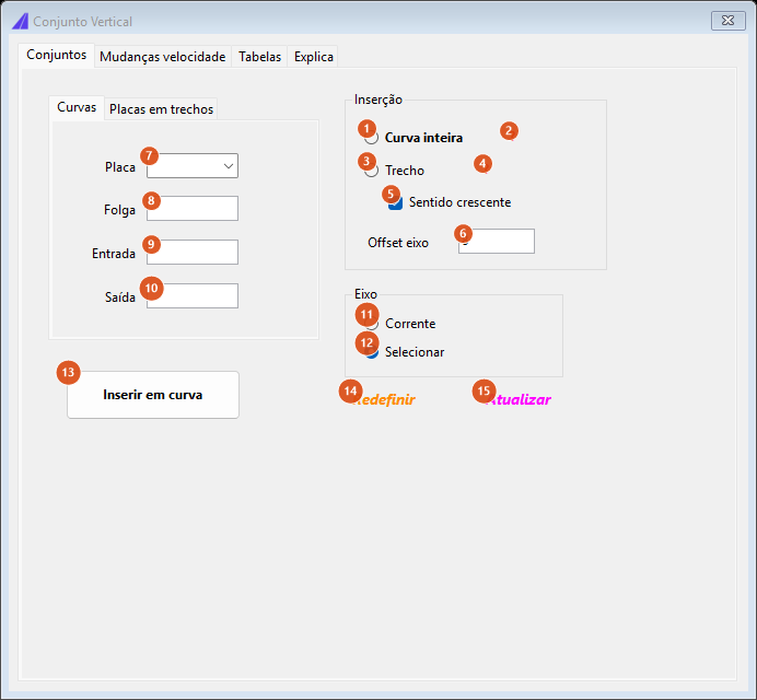
Opening state: the Conjuntos page, Curvas tab. No insertion mode is preselected.
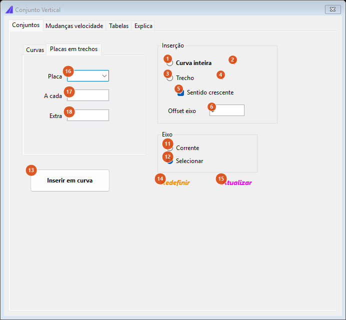
The Placas em trechos tab: the three fields on the left (16 to 18) replace the four on the Curvas tab; everything on the right is shared.
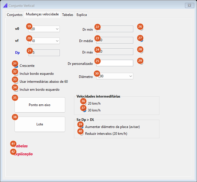
The Mudanças velocidade page: the table readouts on the left and at the top, the method options below.
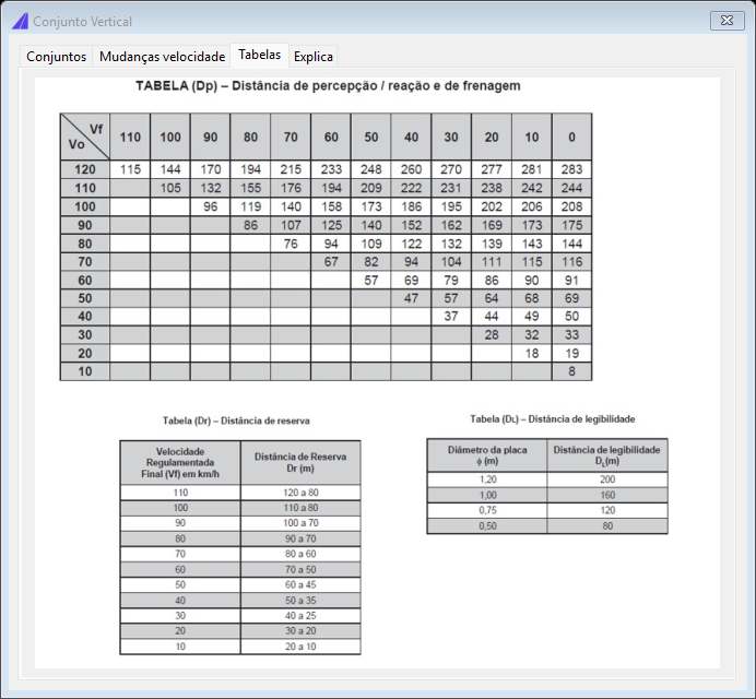
The Tabelas page: the method's three tables (Dp, Dr and DL) as an image, with no controls.
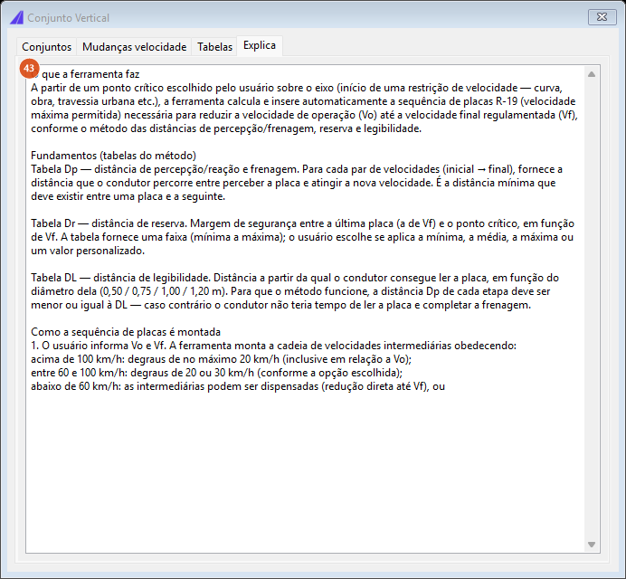
The Explica page (43): the method's text, for reading only.
Conjuntos page, Curvas tab
| # | Control | What it does |
|---|---|---|
| 7 | Placa (Sign) | Lists the five curve-warning codes of the Brazilian profile. Picking one fills Entrada with that code plus A and Saída with the code plus B, and preselects the insertion mode (the first two select Curva inteira, the last three select Trecho). It is only a shortcut: the codes can be typed straight into 9 and 10. |
| 8 | Folga (Gap) | The distance, measured outwards from each end of the stretch, at which each of the two signs is placed: one lands gap metres past the end, the other gap metres before the start. |
| 9 | Entrada (Entry) | Code of the entry sign. It must exist in the sign library; otherwise the command warns "Placa … não encontrada." and inserts nothing. |
| 10 | Saída (Exit) | Code of the exit sign, with the same requirement. |
Which of the two goes to each end depends on the direction of the curve:
| Curvature of the chosen segment | Past the end of the stretch, facing back | Before the start, facing forward |
|---|---|---|
| Left-hand curve | the Saída sign | the Entrada sign |
| Right-hand curve | the Entrada sign | the Saída sign |
The lateral offset of the two signs from the alignment is fixed at 8 units in this version.
Conjuntos page, Placas em trechos tab
| # | Control | What it does |
|---|---|---|
| 16 | Placa (Sign) | Lists two codes; one prefills A cada with 10000 and the other with 500, and both select Trecho. Other codes can be typed. |
| 17 | A cada (Every) | Distance between signs. The command divides the stretch by the value (banker's rounding) and drops one stop; if the result is zero or negative it warns "Trecho selecionado para inserção possui metragem insuficiente" and inserts nothing. |
| 18 | Extra | Value written into the EXTRA attribute of every sign inserted — this is where a speed-limit sign's speed appears on the sign. |
Each station receives two signs, one for each direction of travel, both 8 units off the alignment.
Conjuntos page, the Inserção and Eixo frames (shared by both tabs)
| # | Control | What it does |
|---|---|---|
| 1 | Curva inteira (Whole curve) | After clicking Inserir, you click near a curve and CapCad uses the whole curved segment as the stretch. If the clicked point does not fall on a segment with curvature, the command warns "Curva não encontrada no ponto." |
| 2 | ? | Reminder: the blocks generated are selectable groups. |
| 3 | Trecho (Stretch) | You click two points on the alignment and the stretch between them is used. Clicking the same point twice warns "Mesmo ponto clicado - verifique o osnap". |
| 4 | ? | Reminder: select two points on the alignment; the direction follows the order in which they are clicked. |
| 5 | Sentido crescente (Increasing direction) | Not available in this version: stretch insertion already inserts in both directions, and curve insertion derives the direction from the curvature. |
| 6 | Offset eixo (Alignment offset) | Not available in this version: the lateral offset is fixed at 8 units, the same value the box shows. |
| 11 | Corrente (Current) | Uses the project's active alignment. Disabled when the project has no alignment, and in that case Selecionar selects itself. Hovering shows the alignment name. |
| 12 | Selecionar (Select) | Asks for a curve in the drawing after Inserir is clicked. |
| 13 | Inserir em curva / Inserir em trecho | Runs it. The caption follows the mode chosen in 1 / 3. |
| 14 | Redefinir (Reset) | Erases the entities of the last set drawn. |
| 15 | Atualizar (Update) | Erases the last set and draws it again with the current values. |
Mudanças velocidade page
This page builds a staged speed-reduction chain: from an operating speed v0 down to a regulated final speed vf, it places one speed-limit sign per intermediate step, working back from the critical point. The distances come from three tables — Dp (perception, reaction and braking, per v0 → vf pair), Dr (reserve distance, per final speed) and DL (legibility distance, per sign diameter) — shown as an image on the Tabelas page. The tables and the sign code used are those of the Brazilian profile; the Portuguese edition of this page carries them.
| # | Control | What it does |
|---|---|---|
| 19 | v0 | Operating speed, 120 down to 10 km/h in steps of 10. Changing it reloads the vf list with every speed below it. |
| 20 | vf | The regulated final speed. |
| 21 | Dp (read-only) | Perception/reaction and braking distance for the v0 → vf pair, read from the Dp table. Empty when the pair is not tabulated. |
| 22 | Dr mín (read-only) | Smallest reserve distance tabulated for vf. |
| 23 | Dr média (read-only) | Mean of the smallest and the largest. |
| 24 | Dr máx (read-only) | Largest reserve distance tabulated for vf. |
| 25 | Dr personalizado (Custom Dr) | A free reserve-distance value, used when 29 is selected. |
| 26 to 28 | Dr mín / média / máx | Choose which of the three reserves the chain uses. |
| 29 | Dr personalizado | Uses the value in 25. It is also the fallback: if none of the four is selected, the command treats it as custom. |
| 30 | Diâmetro (Diameter) | Sign diameter in metres: 0.50, 0.75, 1.00 (default) or 1.20. It sets the legibility distance — 80, 120, 160 and 200 m respectively. |
| 31 | Crescente (Increasing) | Builds the chain in the alignment's increasing direction, that is with the signs before the critical point in that direction. Ticked by default. |
| 32 | Incluir bordo esquerdo (Include the left edge) | Also inserts the twin sign on the left edge, at every link of the chain. Applies only to the Ponto em eixo button; Lote does not read this option. |
| 33 | Usar intermediárias abaixo de 60 (Use intermediate steps below 60) | Below 60 km/h the chain normally drops straight to vf. Ticked, the reduction below 60 is staged too, with the step chosen in 36 / 37. |
| 34 | Incluir em bordo esquerdo | Not available in this version. |
| 35 | Ponto em eixo (Point on the alignment) | Hides the form, asks for the critical point on the alignment and inserts the chain. A chain of fewer than two signs is simply not inserted. If any sign would fall outside the alignment's limits, the command warns and stops the insertion. |
| 36, 37 | 20 km/h, 30 km/h | Step between intermediate speeds in the 60 to 100 km/h band (and below 60, if 33 is ticked). Above 100 km/h the step is always 20. Default: 30. |
| 38 | Lote (Batch) | Walks the whole alignment: every change of design speed recorded in the alignment properties becomes a transition, and every transition gets its own chain. At the end it shows the total inserted and the report. Signs falling outside the alignment's limits are skipped, with a warning in the report, without interrupting the pass. With no transitions at all, it warns "Nenhuma transição de velocidade encontrada nas propriedades do eixo." |
| 39 | Aumentar diâmetro da placa (avisar) (Increase the sign diameter — warn) | When the chain's largest Dp exceeds the legibility distance, the command inserts anyway and says which minimum diameter would cover it (1.00 m up to 160 m of Dp, 1.20 m up to 200 m; beyond that, no diameter is enough). Default. |
| 40 | Reduzir intervalos (20 km/h) (Reduce the steps) | The alternative to the previous one: in the same case, the chain is rebuilt with a 20 km/h step and intermediate steps below 60. If Dp still exceeds the legibility distance, the warning appears. |
| 41 | Tabelas (Tables) | Jumps to the Tabelas page. |
| 42 | Explicação (Explanation) | Jumps to the Explica page. |
The Tabelas and Explica pages
| # | Control | What it does |
|---|---|---|
| — | (the Tabelas page) | Only the image of the method's three tables: Dp per speed pair, Dr per final speed and DL per sign diameter. No controls. |
| 43 | Explica | A read-only text box describing the method and the rules for building the chain. |
The other form: Conjuntos de placas
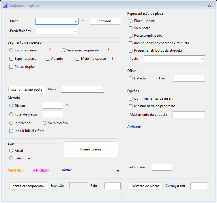
The form CAPCAD_SIGN_SET_PLACE opens when the answer is No — and the only one that appears under a non-Brazilian country profile.
It inserts alignment markers and delineator posts along a curve or a stretch, with presets, radius-based spacing formulae and a representation with or without leader lines. The marker list offers MA, MA-I and CHEVRON; on the drawing the block actually used follows the active country profile, exactly as in Kilometre posts and alignment markers.
Before clicking Inserir placas, click usar o mesmo poste (use the same post): it mirrors the second row of the double assembly, and that combination is what the command needs in order to proceed — with the two rows identical it refuses the insertion with "As duas linhas do conjunto duplo são idênticas." Stretch insertion is not available in this version: it shows the computed plan instead.
How the options combine
The figures below came from the command's own engine, with a reference sign 4 units tall.
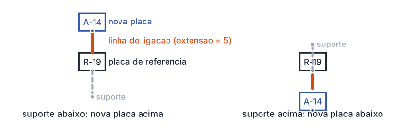
CAPCAD_SIGN_ASSEMBLY with no options: the command looks for the reference sign's post and grows the assembly the other way. On the left, post below and new sign above; on the right, post above and new sign below. With no post found, the default is above.
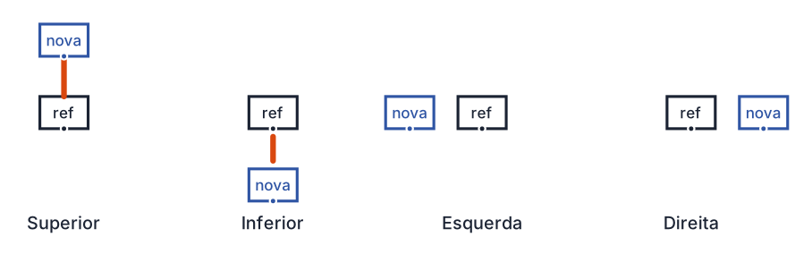
The four keywords of CAPCAD_SIGN_ASSEMBLY_OPTIONS, with a gap of 5. Above and below draw the connecting line; left and right draw nothing between the two signs.
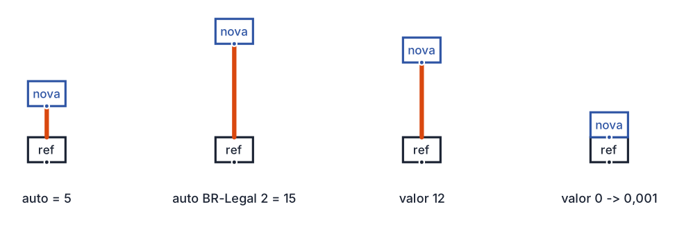
The gap changes only the distance, never the side: 5 for the automatic gap, 15 for the automatic gap under the paradigm that raises it, then a typed value, and the zero case, which becomes 0.001.
Remembered between sessions
CAPCAD_SIGN_ASSEMBLY and CAPCAD_SIGN_ASSEMBLY_OPTIONS keep nothing: code, side and gap are asked for on every run.
The CAPCAD_SIGN_SET_PLACE form stays open and keeps everything you typed for as long as the CAD session lasts — the values are not written to disk, so it comes back to its opening state in the next AutoCAD.
The Ext.linha field on the Conjunto tab of sign insertion is written to the user preferences and restored when the form opens.
Notes
- The reference can be any block. The click accepts any block reference, and the height, the point and the rotation come from it. On a block that is not a sign there are no attributes to inherit and no paired post, so the new sign goes above, with no inherited station or coordinates.
- With no post identified, the assembly grows upwards. Automatic detection uses the post paired with the sign (tolerance of 1 unit). With no post nearby, the new sign goes above.
- Only the second quadrant sends the sign downwards. The detection rule looks at the angle from the sign to the post relative to the sign's own rotation: only the second quadrant puts the new sign below; every other quadrant puts it above.
- The connecting line follows the action. It goes to the implant, keep or remove layer according to the situation of the sign being inserted into the assembly. In a substitution, under the paradigm that has one, it goes to the substitution layer.
- The measured height ignores hatches in this version. The command measures the vertical extent of the inserted block; if the sign carries a hatch taller than its outline, the end of the connecting line ends up slightly displaced.
- Check the post after building an assembly. The second sign is inserted like a new sign, which also draws a post at its point; run Fix Traffic Signs to check the sign-to-post pairing and clear duplicates.
- The in an existing assembly method of sign insertion does the same stacking — sign above the reference, gap 5, no post of its own — but does not draw the connecting line in this version. For the complete assembly, use
CJ. - Related pages: sign insertion, sign actions, swap and substitute, Fix Traffic Signs and sign management.