| Commands | CAPCAD_GEO_GRID (coordinate grid), CAPCAD_GEO_GRID_POINT (points grid), CAPCAD_POINT_TO_COGO (Civil 3D COGO points), CAPCAD_GEO_UK_OS_TILE (OS grid reference) and CAPCAD_GEO_UK_BOUNDARY (UK outline in BNG) |
| Shortcut | none |
| Ribbon | CapCad tab › Geo panel (Geo Tools BR in the Brazil profile) › Topo split button › Coordinate Grid and Points Grid; the coordinate grid also appears on the CAD Utilities panel › Layout split button. The two British commands are on the UK panel › Geo Data split button › Ordnance Survey Tile Identify and UK Limits in BNG, in the United Kingdom profile only. CAPCAD_POINT_TO_COGO has no ribbon button in any profile |
| Categories | CAPCAD_GEO_GRID: GeoData: Topographic Tools · CAPCAD_GEO_GRID_POINT: Horizontal: tools · the two UK commands: none |
| Forms | CoordinateGridForm, title "Coordinate grid", five tabs (modeless); PointsGridForm, title "Points Grid" (modeless); ConvertToCogoForm, title "Converter em Pontos COGO" (modal). CAPCAD_GEO_UK_OS_TILE and CAPCAD_GEO_UK_BOUNDARY have no form |
| Hosts | CAPCAD_GEO_GRID, CAPCAD_GEO_GRID_POINT, CAPCAD_GEO_UK_OS_TILE and CAPCAD_GEO_UK_BOUNDARY: AutoCAD, BricsCAD, GstarCAD, ZWCAD and ARES Commander. CAPCAD_POINT_TO_COGO: AutoCAD Civil 3D only |
| Also opened by | The COGO point conversion… button on the Tools tab of the Civil 3D utilities form (CAPCAD_CIVIL3D_TOOLS) fires CAPCAD_POINT_TO_COGO |
A sheet is only finished when you can read a coordinate off it. CapCad's coordinate grid is not a block pasted over the top: it is clipped by the drawing's own boundary, labelled on all four sides, and rebuilt live on every change of parameter.
- Clipped by the boundary, not by its bounding box. Every grid line is cut exactly where the boundary passes — including on concave boundaries and boundaries with islands, which get two stretches on the same line.
- Live. Changed the spacing, the text height or the prefix? The grid is redrawn at once, over the same boundaries.
- Two label grammars.
X=/Y=,E=/N=, or latitude and longitude in degrees-minutes-seconds, with a thousands separator of your choosing. - Straight onto the viewport. In paper space, the grid can come from the viewport frame, from a reference polyline, or from every viewport of every layout at once.
- A grid of levelled points. Inside a closed boundary, a regular grid of points that can arrive with the Bing Maps elevation already in Z.
- Cleanup tools alongside. Isolate or erase everything on the grid layers, in one click.
What it does
CAPCAD_GEO_GRID opens the Coordinate grid: you select one or more closed boundaries and the command draws, inside each of them, the grid lines at multiples of the chosen spacing, with the coordinate labels along the edges. Every change of parameter rebuilds the grid over the same boundaries, erasing the previous one — which is what makes the form feel like a previewer. In paper space, the boundaries can be the viewports themselves.
CAPCAD_GEO_GRID_POINT opens the Points Grid: inside a closed boundary, a regular grid of POINTs at the chosen spacing, optionally with the Bing Maps elevation in Z — the quick base for an approximate surface, or for checking the relief of a stretch.
CAPCAD_POINT_TO_COGO converts POINTs, attributed blocks or text in the drawing into Civil 3D COGO points, gathered into a point group, with the raw description taken from the attribute, the text or the layer name.
CAPCAD_GEO_UK_OS_TILE and CAPCAD_GEO_UK_BOUNDARY are the two British utilities: the first reads the Ordnance Survey grid reference of every point you click; the second draws the outline of the United Kingdom in BNG — not available in this version; see the Notes.
Everything involving a conversion depends on the drawing's coordinate system — see Coordinates and the coordinate system, and in particular What actually converts.
Workflow
Drawing the coordinate grid
- Run
CAPCAD_GEO_GRID. - Set the Space (11) and, if you want, the style (12/13), the text height (6) and the prefixes (2, 3 — the XY (4) and EN (5) buttons fill in the two usual pairs).
- Click Select boundaries (16). The form hides, you select the closed boundaries in the drawing, and the grid appears.
- From then on, any change to the controls redraws the grid over the same boundaries. The footer reports how many lines and how many labels were drawn, over how many boundaries.
- Reset (17) erases the grid and forgets the selection; Update (18) forces a redraw.
In paper space, choose the mode on the Options tab first (28 to 32): step 3 then asks for viewports instead of boundaries, or asks for nothing at all in All viewports mode.
Creating the points grid
- Run
CAPCAD_GEO_GRID_POINT. - Give the Spacing (35) and decide whether you want the elevations (34).
- Click Create points grid (36) and select the boundary. It must be closed; if it has arcs, the command asks whether to ignore them, tessellate (splitting each arc into 10 chords, and drawing the result) or cancel.
- Without elevations, the points are drawn at once, on the current layer, with Z = 0.
- With elevations, the command asks for the coordinate system (if there is not one yet), says how many points it will process and asks for confirmation, queries Bing Maps in batches of 100 points and draws 3D points on layer
CAPCAD_GEO_POINTS.
Converting points into COGO points
- Open the drawing in Civil 3D and run
CAPCAD_POINT_TO_COGO(or the COGO point conversion… button of the Civil 3D utilities). - In the form, choose the data source: POINT entities, attributed block (INSERT), or TEXT / MTEXT.
- With a block: click Selecionar bloco…, pick an instance in the drawing, and the attribute combo boxes fill with its tags.
- Set the elevation (from the entity's Z, fixed, or forced to zero), the raw description and the point group name.
- Converter. The command asks for the selection, already filtered by the chosen type, creates the COGO points, builds the group and — if you ticked it — erases the original entities.
Reading the OS grid reference
- With the drawing in BNG, run
CAPCAD_GEO_UK_OS_TILE. - Click a point. The 500 m tile reference appears in a box and is copied to the clipboard.
- The command keeps asking for points until you press Esc.
The forms
The numbers are unique on this page: 1 to 33 in the Coordinate grid and 34 to 36 in the Points Grid. All the captures are of a Portuguese session; the numbering is the same in both editions, and the tables give the English captions.
Coordinate grid — CAPCAD_GEO_GRID
The eight footer controls (11 to 18) sit below the tabs and appear on all of them.
Tab 1: Text
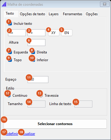
Factory defaults: spacing 100, continuous style, text on all four sides, height 2.
| # | Control | What it does |
|---|---|---|
| 1 | Include text | Switches the labels on. Unticked, it disables 2 to 10 and the grid comes out with no text at all. Ticked by default. |
| 2 | (X axis prefix) | The text preceding the abscissa in the bottom and top labels. Default X=. |
| 3 | (Y axis prefix) | The text preceding the ordinate in the left and right labels. Default Y=. |
| 4 | XY | Fills 2 and 3 with X= and Y=. |
| 5 | EN | Fills 2 and 3 with E= and N= (Easting / Northing). |
| 6 | Height | The label text height, in drawing units. Default 2. It is also the basis of each label's offset from the boundary. |
| 7 | Left | A label at the left end of each horizontal line. |
| 8 | Right | A label at the right end. |
| 9 | Top | A label at the top end of each vertical line. |
| 10 | Bottom | A label at the bottom end. |
| 11 | Space | The grid spacing, in drawing units. Default 100. A comma is accepted as the decimal separator; invalid text falls back to 100. |
| 12 | Continuous | The grid is drawn as whole lines, clipped by the boundary. Default. |
| 13 | Cross | The grid becomes crosses at the line intersections, and the lines are not drawn. |
| 14 | Size | The size of the cross. Only applies in Cross style; zero draws nothing. |
| 15 | Text line | The length of the short tick drawn inwards at each end of a grid line. Only applies in Cross style. |
| 16 | Select boundaries | Hides the form, asks for the boundaries (or the viewports, in paper-space modes) and draws. |
| 17 | Reset | Erases the drawn grid and forgets the selected boundaries. |
| 18 | Update | Redraws with the current values. |
Tab 2: Text options
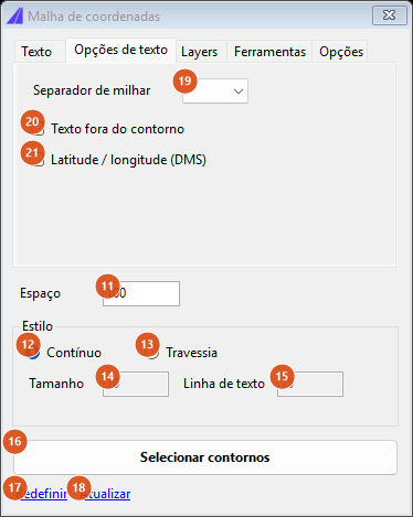
| # | Control | What it does |
|---|---|---|
| 19 | Thousands separator | Three options: blank (no separator — 1234500), , and .. |
| 20 | Text outside the boundary | Places the label outside the boundary, rotated to the edge, instead of inside and horizontal. |
| 21 | Latitude / longitude (DMS) | Labels in degrees-minutes-seconds instead of projected units. Only enabled when the drawing has a coordinate system CapCad can actually convert — see Notes. |
Tab 3: Layers
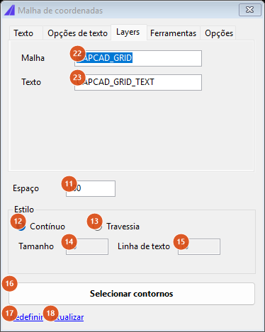
| # | Control | What it does |
|---|---|---|
| 22 | Grid | The layer of the lines and crosses. Default CAPCAD_GRID. |
| 23 | Text | The layer of the labels. Default CAPCAD_GRID_TEXT. |
Both names are also what the tools on the next tab act on.
Tab 4: Tools
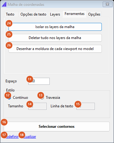
| # | Control | What it does |
|---|---|---|
| 24 | Isolate the grid layers | Switches off every layer in the drawing except the two from 22 and 23. |
| 25 | Delete everything on the grid layers | Asks first, then erases every entity on those two layers — including anything this command did not draw. |
| 26 | Draw every viewport frame in model | Draws, in model space, the frame of every viewport of every layout, on the grid layer. |
Tab 5: Options
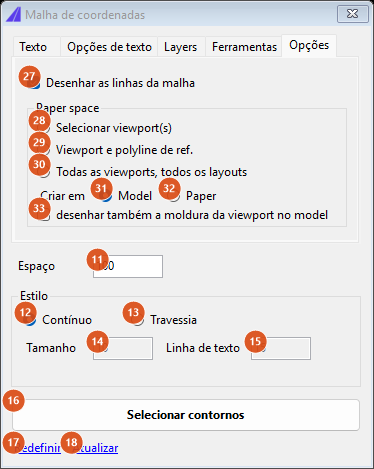
The Paper space frame is only active while you are on a layout; in model space it is disabled and its caption says why.
| # | Control | What it does |
|---|---|---|
| 27 | Draw the grid lines | Draws the whole lines. It is independent of the style: unticking it removes the lines even in Continuous style, leaving only the labels (and the crosses, in Cross style). Ticked by default. |
| 28 | Select viewport(s) | The boundary comes from the frame of the viewports you select. |
| 29 | Viewport and ref. polyline | The boundary comes from the viewport's clipping polyline, not from its rectangle. |
| 30 | All viewports, all layouts | Nothing is selected: the command walks every viewport of every layout. |
| 31 | Model | The grid is drawn in model space, in model coordinates. |
| 32 | Paper | The grid is transformed to the layout and drawn in paper space. |
| 33 | also draw the viewport frame in model | Besides the grid, draws each treated viewport's frame in model, on the grid layer. |
Careful. The five radio buttons 28 to 32 sit in the same frame and therefore form one single exclusive group: choosing Paper unticks the viewport selection mode, and choosing a viewport mode unticks Model / Paper. In this version you cannot combine, say, All viewports with Paper. See Notes.
Points Grid — CAPCAD_GEO_GRID_POINT
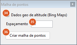
| # | Control | What it does |
|---|---|---|
| 34 | Altitude geo data (Bing Maps) | Queries each point's elevation from Bing Maps and draws 3D points. Unticked, the points come out with Z = 0. |
| 35 | Spacing | The grid step, in drawing units. Default 20; a comma is accepted; an invalid or non-positive value falls back to 20. |
| 36 | Create points grid | Hides the form, asks for the boundary and draws. |
Converter em Pontos COGO — CAPCAD_POINT_TO_COGO
There is no screenshot of this form on this page. It shows Portuguese captions — everything below is quoted in Portuguese, as the form shows it, with a gloss. The controls, in five frames:
| Frame | Controls |
|---|---|
| Origem dos dados [data source] | Entidades POINT (default), Bloco com atributos (INSERT) [attributed block] and TEXT / MTEXT. With a block: Selecionar bloco… [select block], the recognised block name, Atributo de número [number attribute] with a Sequencial box beside it, and Atributo de descrição [description attribute] with a Nenhum [none] box. With text: Usar o conteúdo do texto como descrição bruta [use the text content as the raw description], ticked by default. |
| Substituições de descrição [description overrides] | Usar o nome do layer como descrição bruta (substitui atributo / texto); Avisar sobre coordenadas XY duplicadas [warn about duplicate XY coordinates] (ticked by default) with Tol. (m), default 0.001. |
| Numeração [numbering] | Número inicial [start number] (default 1), Prefixo and Sufixo, with the hint EST-001-A → prefixo="EST-" sufixo="-A". See Notes: in this version these three fields never reach the COGO point created. |
| Elevação | Usar o valor Z da entidade [use the entity's Z] (default), Elevação fixa: with a value box in metres, and Forçar Z = 0. |
| Saída [output] | Grupo de pontos [point group] (default CapCad_Import) and Apagar as entidades originais após a conversão [erase the original entities after conversion], unticked by default. |
The Converter button validates before closing: the fixed elevation and the tolerance have to be numbers, the group name cannot be empty, and the Bloco source requires that a block has already been selected.
How the options combine
How the grid is built
The command does not draw a lattice over the boundary: it clips. For each ordinate at a multiple of the spacing, an infinite line is intersected with the boundary, the intersections are sorted along the axis and paired two by two — each pair is a stretch on the inside. That is where the correct behaviour on concave boundaries and boundaries with islands comes from: a line crossing the "mouth" of a C-shaped boundary gets two segments, not one.
The first ordinate is the first multiple of the spacing strictly above the bottom (or left) side of the bounding box. The two axes are not symmetrical: the top line can be missing where the right-hand column appears.
When each label is drawn
The length of the stretch decides, and the thresholds are asymmetrical:
| Label | Only when the stretch is longer than |
|---|---|
| Left | 40 units |
| Right | 20 units |
| Bottom | 20 units |
| Top | 40 units |
So a short stretch (between 20 and 40) gets exactly one label — the right-hand or the bottom one. Each label is then shifted along its own axis by height × 1.333 × cot(θ) (or tan(θ) on the verticals), θ being the boundary's direction at the crossing, so that it does not collide with a sloping edge.
What the style and the line boxes combine to
| Style (12/13) | Draw the grid lines (27) | Size (14) | Text line (15) | Result |
|---|---|---|---|---|
| Continuous | ticked | ignored | ignored | whole lines, clipped |
| Continuous | unticked | ignored | ignored | labels only |
| Cross | either | > 0 | 0 | crosses at the intersections |
| Cross | either | > 0 | > 0 | crosses and the short ticks at the line ends |
| Cross | either | 0 | 0 | nothing — the form warns that there is nothing to draw when there is no text either |
The points grid and Bing Maps
The grid starts at the integer floor of the bounding box's lower-left corner and advances by the spacing on both axes, keeping only the nodes that fall inside the boundary. With the elevations switched on, the points are reprojected to latitude/longitude and sent to Bing Maps in batches of 100, with progress on the command line. A reprojection or network failure aborts the whole run — not even the points already processed are drawn. The 3D points come out on layer CAPCAD_GEO_POINTS, ACI colour 8.
The Ordnance Survey grid reference
CAPCAD_GEO_UK_OS_TILE treats the clicked point's coordinates as if they already were British National Grid easting and northing: there is no conversion at all. The reference returned is that of the 500 m tile — two letters, four digits and the quadrant suffix (NE, NW, SE, SW). A point outside the letter grid returns "Outside the OS grid."
Remembered between sessions
The Points Grid keeps the elevation box and the spacing. The Coordinate grid keeps nothing: every opening reloads the factory defaults listed in the tables above. The Converter em Pontos COGO form keeps nothing either: it always opens at the factory defaults.
Notes
CAPCAD_GEO_UK_BOUNDARYis not available in this version. The run stops with the message "BNG conversion failed". The same happens in every GIS command in which you chooseBNGin the coordinate-system box — andBNGis what the United Kingdom profile hands out as its default when nothing else is set.- The coordinate-system box offers more than it converts.
WGS-84,BNGand the 120 zonesUTM-01StoUTM-60Nappear in the list, but only SIRGAS 2000 and SAD 69 over zones 17 to 25 South and 11 to 22 North are actually resolved. That is why the Latitude / longitude (DMS) box (21) is disabled in drawings outside that coverage: the form tests the conversion of a sample point on opening and, if it fails, switches the option off and says so on the command line. It is also disabled when there is no coordinate system set, and when the system isWGS-84— the drawing is already in degrees then. - In latitude/longitude mode, all four sides show the LATITUDE. The top and bottom labels — the X axis — show the latitude too, not the longitude. If you need the longitude, label in projected coordinates.
- The paper-space modes do not combine. The five radio buttons on the Options tab (28 to 32) share a single group, so Select viewport(s) / Viewport and ref. polyline / All viewports and Model / Paper cancel each other out. On opening the form, the effective default ends up being Model with no viewport mode ticked.
- A north arrow and a text-style selector are not available in this version. The text comes out in the drawing's current style.
- A boundary that is not closed produces no points grid.
CAPCAD_GEO_GRID_POINTrefuses open geometry with a message saying it must be closed. A boundary with arcs asks first: ignore and continue, cancel, or tessellate — tessellation splits each arc into 10 chords and draws the tessellated curve in the drawing. - Without elevations, the points grid ignores the
CAPCAD_GEO_POINTSlayer. The points go onto the current layer; only the elevation path creates and uses the dedicated layer. - The OS reference is only reliable with six-digit values. The reference's four digits are cut from positions 2 and 3 of the easting and the northing written as text. Coordinates with fewer than six integer digits produce a reference shifted by one place. The command also always uses the 500 m tile.
CAPCAD_POINT_TO_COGOrequires AutoCAD Civil 3D — not just AutoCAD — and does not exist on the other four CADs.- The COGO form's numbering never reaches the point created. Número inicial, Prefixo, Sufixo and the number attribute are only used to build the labels in the duplicate-check messages; the COGO point's number is whatever Civil 3D assigns on creation. The point group, on the other hand, is built with the real numbers.
- The duplicate-number confirmation does not list the numbers. When the command detects repeated numbers, the confirmation box asks whether to continue — Yes carries on discarding the duplicates, No cancels — but the text does not say which numbers collided.
- The duplicate-XY check is slow on large selections. It compares every pair in the selection; on very large selections the command visibly stalls between the selection and the creation of the points. Untick Avisar sobre coordenadas XY duplicadas if you do not need it.
- Bing Maps is an external service. The points grid with elevations depends on the network and on the elevation service answering; any error is reported and the run is abandoned.